


88
A
B
C
A
B
A
B
C
15' (4,6 m)
10' (3 m)
fi g. 6.10
fi g. 6.11
fi g. 6.12
fi g. 6.13
6 - L
OAD
C
APACITIES
Load Capacities
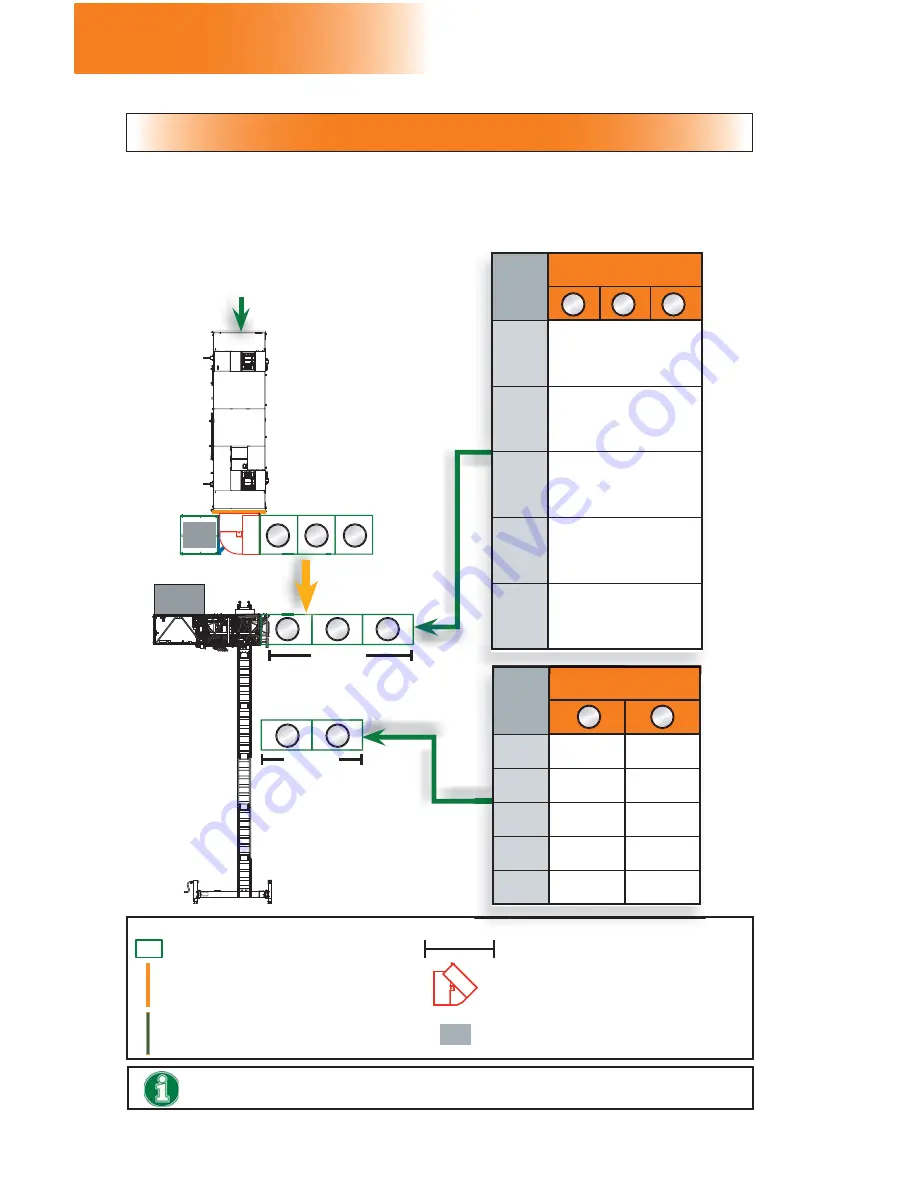
Swivel bridge installation on a 24' (7,3 m) motorized unit
Swivel bridge installation on a 24' (7,3 m) motorized unit
Single unit with counterweight adapter — Front 90 degrees
Single unit with counterweight adapter — Front 90 degrees
LEGEND
5' (1,5 m) square bridge assembly
Length of bridge setup
Square bridge adapter
Swivel bridge
Counterweight adapter
Counterweight
To ensure safety at all times, refer to load calculation guidelines and warnings on
p. 80.
CW
CW
3
CW
Load capacities for two
bridges
300 lb
(136 kg)
1000 lb
(453 kg)
1000 lb
(453 kg)
500 lb
(227 kg)
1500 lb
(680 kg)
1000 lb
(453 kg)
500 lb
(227 kg)
2000 lb
(907 kg)
750 lb
(340 kg)
1000 lb
(453 kg)
1500 lb
(680 kg)
1250 lb
(567 kg)
1000 lb
(453 kg)
1950 lb
(885 kg)
1000 lb
(453 kg)
At this end, it is mandatory to install a bridge
. The
only
bridge configurations allowed
are a cantilever bridge
measuring
at least
5' (1,5 m) and a
maximum
of 10' (3 m)
with capacities as shown in the load capacities charts for
single unit setups (see fi g. 6.2, p. 81)
—
OR
—
any bearing bridge confi guration shown in the load capacities
charts for multiple unit setups (see fi g. 6.3, p. 82).
es
CW
Load capacities for three
bridges
300 lb
(136 kg)
9 0 0 l b ( 4 0 8 k g )
e v e n l y
distributed
on three bridges
— OR —
600 lb (272 kg) on
one
of the
three bridges
800 lb
(363 kg)
1200 lb (544 kg)
evenly
distributed
on three bridges
— OR —
800 lb (363 kg) on
one
of the
three bridges
1100 lb
(499 kg)
1400 lb (635 kg)
evenly
distributed
on three bridges
— OR —
950 lb (431 kg) on
one
of the
three bridges
1500 lb
(680 kg)
1700 lb (771 kg)
evenly
distributed
on three bridges
— OR —
1150 lb (522 kg) on
one
of the
three bridges
1600 lb
(726 kg)
1800 lb (816 kg)
evenly
distributed
on three bridges
— OR —
1200 lb (544 kg) on
one
of the
three bridges
A
B
C
A
B
CW
NO OTHER CONFIGURATION THAN THOSE ABOVE ARE
ALLOWED AT THIS END


