32
CLEAN RECOVERY TANK DRAIN
Debris and sand accumulation in the drain valve can damage the valve or prevent it from closing completely.
This will result in dirty water leaking from the valve. Use of the Hydro-Filter and regular cleaning of the
recovery tank will help prevent this, but occasionally the drain valve will require cleaning or replacement.
Unplug both power cords and drain the recovery tank before attempting to service
the drain valve.
•
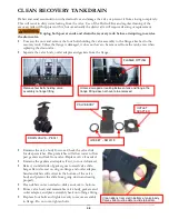
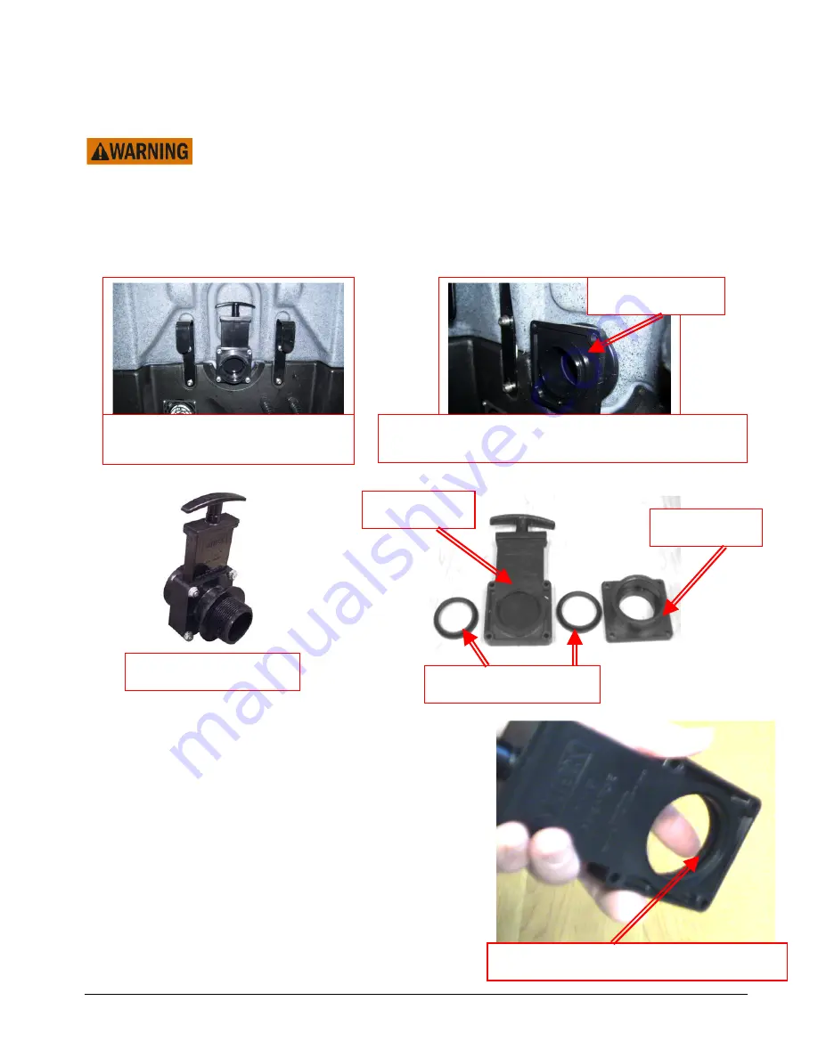
Unscrew the nuts and remove the four bolts holding the valve assembly to the flange attached to the
recovery tank. Unless the flange is damaged, it does not have to be removed from the tank, even when
replacing the drain valve.
•
Separate the valve body, outlet adapter and gaskets from the flange.
•
Examine the valve body for wear. Check the valve slide
for deep scratches. Deep scratches will allow water to flow
past gaskets and leak from valve. Replace valve if needed.
•
Examine the gaskets and replace if cut, torn or deformed.
•
Raised, rounded side of gasket goes toward valve slide.
Larger flat sides seat on ring on flange and outlet adapter.
Sand and debris will collect in the bottom of the valve
body and prevent the slide from going down and seating
properly.
•
Clean debris out as needed so slide can move to bottom.
•
Rinse valve body and reassemble valve body, gaskets and
outlet adapter, and place assembly back onto flange fitting.
•
Replace four bolts and tighten evenly to secure assembly
to flange. Do not over-tighten bolts.
Remove four bolts holding valve
assembly to flange fitting
Unless damaged or leaking between tank and flange, the
flange fitting does not have to be removed
FLANGE FITTING
GASKET – NM3019
VALVE BODY
OUTLET
ADAPTER
DRAIN VALVE – PEA11
Clean debris from slot in bottom of valve body.
Valve slide must be able to slide to bottom.
Summary of Contents for Nautilus MX3-200HE
Page 1: ...1 LMANN09 Revised 02 16 2018 Nautilus MX3 200HE Operating Manual ...
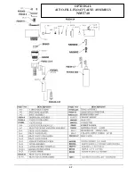
Page 37: ...37 OPTIONAL AUTO FILL FLOAT VALVE ASSEMBLY NM5740 ...
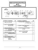
Page 38: ...38 Optional Pump Out Pump AP37 PARTS ASSEMBLY ...
Page 39: ...39 1 2 6 7 8 9 11 3 8 9 12 4 4 3 10 5 15A 8 9 8 9 39 2 ...
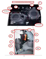
Page 43: ...43 48 49 49 47 47 47A 47 47 47A 47A 51 51 37 9 54 64 52 VACUUM MOUNTS CONNECTIONS 9 54 64 ...
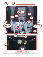
Page 48: ...48 96 91 97 9 94 105 OPTIONAL PUMP OUT CONNECTIONS 99 95 93 103 ...
Page 49: ...49 FLOW 81 92 91 99 96 97 105 13 14A 14 95 OPTIONAL PUMP OUT PARTS 1 9 97 103 39 9 ...
Page 50: ...50 HEATER PARTS 111 113 114 112 2 115 2 116 2 42 42A 98 111 ...

