2.8
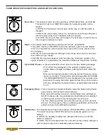
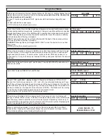
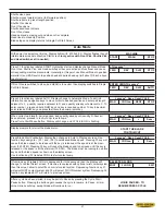
- Shuttle vise opens
- Shuttle moves towards Home (full forward position)
- Shuttle retracts to preset length position
- Shuttle Vise closes
- Front Vise opens
- Shuttle advances to Home
- Front Vise closes
- Head descends, making cut
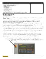
- When cut is complete
- The blade motors shut down
- Display returns to Single Cut Start Screen and hydraulic pump motor will run for a pre-
set time of Power Down Timer. If it is set to 0 then hydraulic pump will shoot off.
PLC 100 CONTROL SYSTEM
OPERATION OVERVIEW
The PLC is a programmable logic controler that allows the operator to run the machine in both manual and
automatic modes
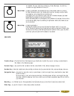
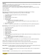
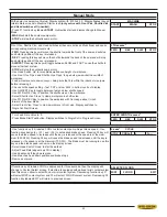
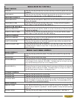
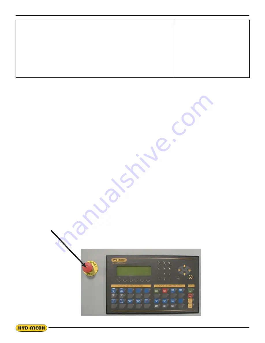
The control panel is divided into four parts: NANUAL ONLY on the left; MANUAL & AUTO in the center;
MACHINE on the right; and NUMERIC and CURSOR keys at the top right. All of these as well as the
EMERGENCY STOP button detailed descriptions follow.
To power up the control panel, the EMERGENCY STOP button must be pulled out. The display screen will
VFUROOWKURXJKVHYHUDODFUHHQVDQG¿QDOO\GLVSOD\LQWKH0$18$/02'(ZLWKWKHGLVSOD\GLPPHG3UHVVLQJ
any key will bring the control panel to full ON and the display backlight will come ON.
Once the control panel has power, the MACHINE START key must be pressed to activate the interface, which
will also start the hydraulic system. Now all of the control keys have been activated and each key has an LED
to indicate which functions are active.
In MANUAL MODE, the operator has the ability to execute a single cut utilizing a pre-programmed SINGLE
CUT MODE.
In AUTOMATIC MODE, the PLC has the capacity to program and store 999 jobs. Designated job numbers
can be programmed for the quantity required (maximum 999 pieces). Piece lengths range from 0” to 500”
(12700mm). Jobs can be run individually or in QUEUE, which allows a maximum of 10 jobs to run
consecutively.
NOTE
If an emergency situation arises during any operation, use the large red
mushroom EMERGENCY STOP button located on the control panel to shut down
the machine
Summary of Contents for S-20 A
Page 2: ......
Page 16: ...1 4 ...
Page 54: ......
Page 55: ...4 1 SECTION 4 ELECTRICAL MAIN PANEL COMPONENT LAYOUT ...
Page 58: ...4 4 MAIN PANEL COMPONENT LAYOUT 1OL 2OL VFD 1M 2M POWER SUPPLY ...
Page 63: ...5 3 FOR HYDRAULIC SCHEMATICS AND PLUMBING DIAGRAMS SEE PDF ON ATTACHED CD ...
Page 64: ......
Page 65: ...6 1 SECTION 6 MECHANICAL ASSEMBLIES For Mechanical Assembly Drawings see PDF on attached CD ...
Page 66: ......
Page 70: ......
Page 72: ...8 2 ...
Page 73: ...8 3 ...
Page 74: ...8 4 ...
Page 76: ...8 6 ...
Page 77: ...8 7 ...
Page 78: ...8 8 ...

