2.13
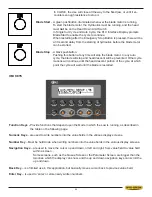
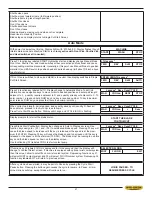
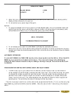
JOB A #
xxxREQ
xxxPcs
LENGTH xxxxx
JOB B #
xxxREQ
xxxPcs
LENGTH xxxxx
JOB C #
xxxREQ
xxxPcs
LENGTH xxxxx
JOB D #
xxxREQ
xxxPcs
LENGTH xxxxx
JOB E #
xxxREQ
xxxPcs
LENGTH xxxxx
JOB F #
xxxREQ
xxxPcs
LENGTH xxxxx
JOB G #
xxxREQ
xxxPcs
LENGTH xxxxx
JOB H #
xxxREQ
xxxPcs
LENGTH xxxxx
WORKING WITH A QUEUE
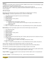
The purpose of a QUEUE is to allow the operator to run several jobs (maximum of 10) in series if they are of
the same material and shape.
To run a QUEUE, it is necessary to program in all job values as is done with programming a single job. After
WKHMREVDUHSURJUDPPHGLQSUHVV48(8(SUHVV&/($5WRFOHDUWKH48(8(DQGHQWHUWKHGHVLUHG-2%¶V
in the desired sequence.
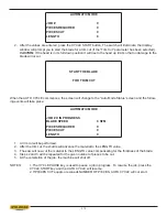
7RUXQWKH48(8(SUHVV&<&/(67$57,IWKHEODGHLVQRWUXQQLQJ%/$'(ZLOOÀDVK3UHVVWKH%/$'(
START key and then CYCLE START. The JOB PROGRESS screen will appear and display each individual
JOB as it is being run.
At the completion of the last job in the QUEUE, the machine will shut off if “0” has been entered in the POWER
':17,0(5SDUDPHWHURUFRQWLQXHUXQQLQJWKHVSHFL¿HGWLPHXSWRDPD[LPXPRIPLQXWHV7KHPDFKLQH
will automatically advance the stock between jobs for trim cuts as needed.
WORKING WITH A REPEATING QUEUE
The QUEUE mode can also be set to repeat the sequence of jobs up to 99 times. To do this the QUEUE
parameter in SERVICE mode must be set at REPEAT.
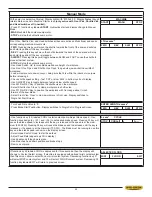
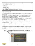
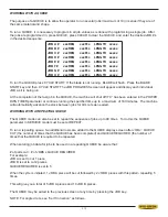
To run a repeating queue, two additional rows are added to the QUEUE display screen after JOB J: QUEUE
CUT (the number of times that the QUEUE has been completed) and QUEUE REQUIRED (the number of
times that the QUEUE is required to be repeated.
When entering job data for jobs to be used in a repeating QUEUE be aware that:
# of parts cut = # of JOBS x QUEUE REQUIRED
For example:
JOB A is set to cut 1 piece
JOB B is set to cut 2 pieces
QUEUE REQUIRED is set to 5
When the cycle is initiated, 1 JOB A piece will be cut followed by 2 JOB B pieces with this pattern repeating 5
times.
This will give you a total of 5 JOB A pieces and 10 JOB B pieces.
The QUEUE may be exited to the previous screen at any time by pressing the JOB key.
NOTE: For angled cuts, see “Kerf Correction” as follows.
Summary of Contents for S-20 A
Page 2: ......
Page 16: ...1 4 ...
Page 54: ......
Page 55: ...4 1 SECTION 4 ELECTRICAL MAIN PANEL COMPONENT LAYOUT ...
Page 58: ...4 4 MAIN PANEL COMPONENT LAYOUT 1OL 2OL VFD 1M 2M POWER SUPPLY ...
Page 63: ...5 3 FOR HYDRAULIC SCHEMATICS AND PLUMBING DIAGRAMS SEE PDF ON ATTACHED CD ...
Page 64: ......
Page 65: ...6 1 SECTION 6 MECHANICAL ASSEMBLIES For Mechanical Assembly Drawings see PDF on attached CD ...
Page 66: ......
Page 70: ......
Page 72: ...8 2 ...
Page 73: ...8 3 ...
Page 74: ...8 4 ...
Page 76: ...8 6 ...
Page 77: ...8 7 ...
Page 78: ...8 8 ...

