2.20
cept where there is a vibration problem. If the blade vibrates appreciable at optimum speed as
most often occurs with structurals and bundles, a lower blade speed may reduce vibration and
prevent premature blade failure.
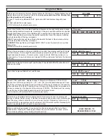
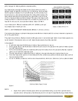
2. Material Hardness – The graph above illustrates blade speed curves for materials of hardness
20 RC (225 Bhn) or lower. If the material is hardened then the multipliers need to be used.
These multipliers are given in the NOTE at the bottom right of the graph.
As the hardness increases the optimum blade speed decreases.
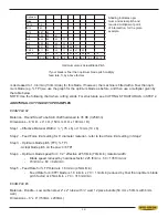
The following table gives examples of the optimum blade speeds for different materials.
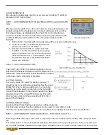
STEP 5 – DETERMINE FEED RATE SETTING (FR) (in./min.) (mm/min.)
FEED RATE is the vertical speed at which the blade descends through the work piece
The FEED RATE knob controls FEED RATE of the blade descent in the range of 0 to 15
in. per minute (380mm/min.) The FEED RATE should be adjusted only in one direction
(from “0” to required value). If you turn too far, the knob
should be turned back to “0” and back to the required
value. To set FEED RATE for particular cutting situations,
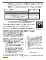
use the graph below, which represents the relationship
between FEED RATE, blade speed and blade pitch.
For Example #1, it is known from STEP 3 that optimum
blade pitch is 2/3, and from STEP 4 that blade speed is
200 ft./min. (60m/min.). From the graph on the left, the
FEED RATE is determined in the following way:
x
2QWKHKRUL]RQWDOD[LVEODGHVSHHGD[LV¿QG
ft./min. (60m/min)
x
Find the point where a vertical line from 200 ft/min
(60m/min) would intersect the 2/3 blade pitch
curve
x
From this intersection point run horizontally left
to the vertical (FEED RATE) axis, to arrive at 1.8
in/min (45mm/min) FEED RATE. Thus, 1.8 in/min
(45mm/min) is the FEED RATE for cutting 8”
(200mm) diameter 1045 Carbon Steel when the
optimum 2/3 pitch blade is used
,IWKHVDZLV¿WWHGZLWKDEODGHFRDUVHUWKDQRSWLPXPHJ
73,ZHFDQVWLOOXVHWKHJUDSKEXWZHJRWRWKHFXUYH$VDUHVXOWZH¿QGWKDWWKH)(('5$7(
Feed Rate Knob
Feed Rate Calculation
Materials and Blade Speed
NO.
MATERIALS
OPTIMUM BLADE SPEED
ft/min
m/min
1
5” (125mm) Dia Solid Carbon Steel
225
70
2
12” (300mm) I-Beam
290
90
3
4” x 4”(100 x 100mm) Rec Tube, 1/4” (6mm) Wall
350
110
4
4”(100) 400 Stainless Steel
140
45
5
2” x 2” (50 x 50mm) Rec Tube 1/4” (6mm) Wall
Bundle 5 x 5 pcs 10” x 10” (500 x 500mm)
325
100
6
3” x 3” (75 x 75mm) Inconel
60
20
Summary of Contents for S-20 A
Page 2: ......
Page 16: ...1 4 ...
Page 54: ......
Page 55: ...4 1 SECTION 4 ELECTRICAL MAIN PANEL COMPONENT LAYOUT ...
Page 58: ...4 4 MAIN PANEL COMPONENT LAYOUT 1OL 2OL VFD 1M 2M POWER SUPPLY ...
Page 63: ...5 3 FOR HYDRAULIC SCHEMATICS AND PLUMBING DIAGRAMS SEE PDF ON ATTACHED CD ...
Page 64: ......
Page 65: ...6 1 SECTION 6 MECHANICAL ASSEMBLIES For Mechanical Assembly Drawings see PDF on attached CD ...
Page 66: ......
Page 70: ......
Page 72: ...8 2 ...
Page 73: ...8 3 ...
Page 74: ...8 4 ...
Page 76: ...8 6 ...
Page 77: ...8 7 ...
Page 78: ...8 8 ...

