3.14
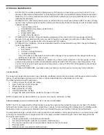
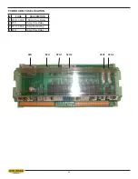
Input/Output Terminal Information
Inputs
X0 – Shuttle Encoder, Channel A – (Open on “P”) X10 – Open (Shuttle Vise Close on Seq. and “P”)
X1 – Shuttle Encoder, Channel B – (Open on “P”) X11 – Open (Shuttle Vise Open on Seq. and “P”)
X2 – Blade Speed
X12 – Open (Front Vise Close on Seq. and “P”)
X3 – Door safety interlock
X13 – Open (Front Vise Open on Seq. and “P”)
X4 – Open (Blade Stop on Seq. and “P”)
X14 – Open (Head Raise on Seq. and “P”)
X5 – Head Lower L/S
X15 – Open (Head Lower on Seq. and “P”)
X6 – Head Raise L/S
X16 – Open (Blade Start on Seq. and “P”)
X7 – Out of stock L/S – (Open on “P”)
X17 – Open (Blade Stop on Seq. and “P”)
Outputs
Y0 – Hydraulic Motor Contactor
Y10 – Front Vise Close
Y1 – Blade Motor Contactor
Y11 – Front Vise Open
Y2 – Mist Option
Y12 – Shuttle Vise Close – (Open on “P”)
Y3 – Blade start
Y13 – Shuttle Vise Open – (Open on “P”)
Y4 – Blade speed increase
Y14 – Shuttle Rev – (Open on “P”)
Y5 – Blade speed decrease
Y15 – Shuttle Fwd – (Open on “P”)
Y6 – Coolant pump On/Off
Y16 – Head Raise
Y7 – Shuttle Fast – (Open on “P”)
Y17 – Head Lower Relay
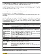
CALIBRATION PROCEDURE
For Mitsubishi PLC100 with 2100 Series software
Length calibration may be achieved in two ways: by inputting the ACTUAL LENGTH or LENGTH CONSTANT parameter.
1. To determine ACTUAL LENGTH value, use MANUAL MODE to position a piece of material, which is approx. 5”
longer that the shuttle full stroke length (i.e. S20A = 34.00”) and close the front vise. Start the blade and make
a trim cut. Raise the head and fully retract the shuttle. Clamp the material and move the shuttle fully forward.
Make a cut and measure the part length.
In SERVICE MODE, move the cursor to the ACTUAL LENGTH parameter and enter the length of the cut part plus
the actual kerf value. Then exit the parameters by pressing the RETURN key.
NOTE: When entering the ACTUAL LENGTH, always round down.
2. To determine LENGTH CONSTANT value, use this formula:
LENGTH CONSTANT = ENCODER PINION CIRCUMFERENCE (TTd)
y
ENCODER RESOLUTION
Example:
For a 1” pinion diameter and 2500 PPR encoder:
LTH CONST = TTd
y
2500 PPR = 0.0012567
TO CHECK LENGTH CONTROL CONSISTENCY:
a. Perform test cuts of three different lengths (i.e. 1”, 12”, 20”) and measure as accurately as possible with a Vernier
or dial caliper
b. If the measurements indicate a linear problem (measured length error increases as the programmed length in-
creases), the ACTUAL LENGTH or LENGTH CONSTANT value will have to be adjusted.
x
If part length error gets longer as the programmed length increases, ACTUAL LENGTH value should be de-
creased
x
If part length error gets shorter as the programmed length increases, ACTUAL LENGTH value should be in-
creased
x
Make small adjustments at a time (i.e. .020” - .030”) and recheck with test cuts
Summary of Contents for S-20 A
Page 2: ......
Page 16: ...1 4 ...
Page 54: ......
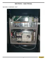
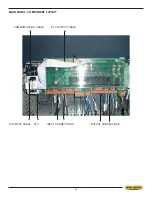
Page 55: ...4 1 SECTION 4 ELECTRICAL MAIN PANEL COMPONENT LAYOUT ...
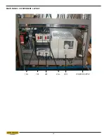
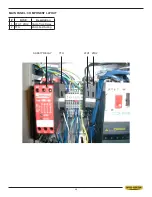
Page 58: ...4 4 MAIN PANEL COMPONENT LAYOUT 1OL 2OL VFD 1M 2M POWER SUPPLY ...
Page 63: ...5 3 FOR HYDRAULIC SCHEMATICS AND PLUMBING DIAGRAMS SEE PDF ON ATTACHED CD ...
Page 64: ......
Page 65: ...6 1 SECTION 6 MECHANICAL ASSEMBLIES For Mechanical Assembly Drawings see PDF on attached CD ...
Page 66: ......
Page 70: ......
Page 72: ...8 2 ...
Page 73: ...8 3 ...
Page 74: ...8 4 ...
Page 76: ...8 6 ...
Page 77: ...8 7 ...
Page 78: ...8 8 ...

