


2.0
STEP 3, DETERMINE OPTIMUM BLADE PITCH - TEETH PER INCH (T.P.I.)
Selecting a blade with proper tooth pitch is important in order to achieve
optimal cutting rates and good blade life.
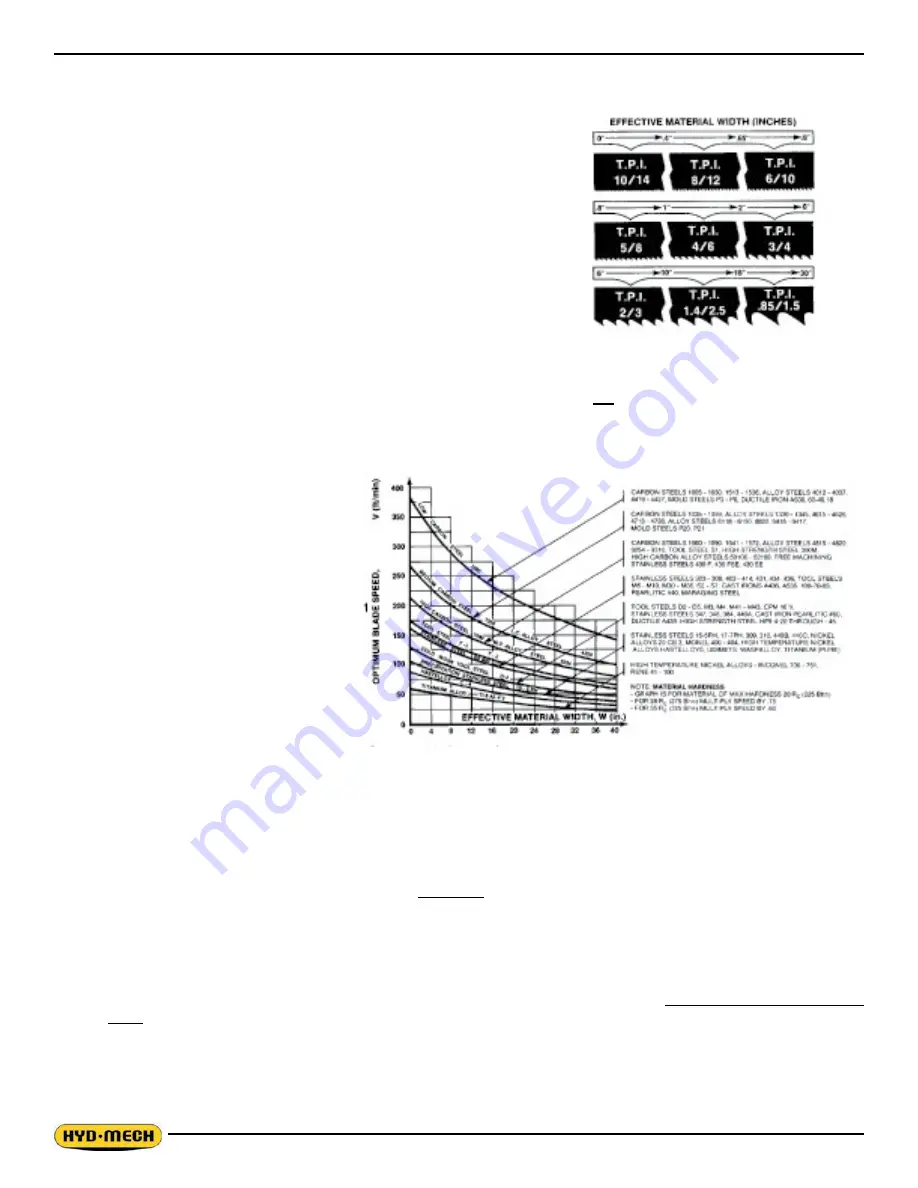
For cutting narrow or thin wall structural materials a fine blade with many
teeth per inch (T.P.I.) is recommended. For wide materials a blade with a
coarse pitch should be used. The sketch can be referenced for the blade
pitch changes for differing effective material widths.
It is impractical to change the blade to the proper pitch every time a dif-
ferent width of material is cut and it is not necessary, but remember that
the optimum blade will cut most efficiently. Too fine a blade must be fed
slower on wide material because the small gullets between the teeth will
get packed with chips before they get across and out of the cut. Too coarse
a blade must be fed slower because it has fewer teeth cutting and there is
a limit to the depth of a cut taken by each tooth. Allowance for the use of a
non-optimum blade is made in STEP 5.
In our Example #: Effective material width of 8” (200 mm) & Optimum blade has 2/3 teeth per inch.
Optimum Blade Pitch ( T.P.I.
Optimum Blade Speed Curves
STEP 4, DETERMINE OPTIMUM BLADE
SPEED, V (ft/min) (m/min)
The relationship between optimum blade
speed and effective material width for vari-
ous materials is represented on the graph
shown.
The graph shows that as effective material
width gets wider or as material gets harder,
lower blade speeds are recommended. If
material is narrow or soft, higher blades
speeds should be selected.
In Example #
•
8” (200mm) diameter #045 Me-
dium Carbon Steel solid bar is to be
cut.
•
On the graph above find the Me
-
dium Carbon Steel Curve which
represents the optimum blade speeds for 045 Carbon Steel.
•
On the horizontal axis (effective material width axis) find number 8 which represents effective material width of an
8” (200mm) diameter solid.
•
Find the point where a vertical line from 8” (200mm) intersects the Medium Carbon Steel Curve.
•
From this intersection point run horizontally left to the vertical axis (optimum blade speed axis) and find the point
marked “200”.
For 8” (200mm) diameter, 045 Carbon Steel solid bar 200 ft/min (60m/min) is the optimum blade speed.
NOTE:
. Higher than optimum blade speed will cause rapid blade dulling. Lower than optimum blade speeds reduce
cutting rates proportionately and do not result in significantly longer blade life except where there is a vibration
problem. If the blade vibrates appreciably at optimum speed as most often occurs with structurals and bundles, a
lower blade speed may reduce vibration and prevent premature blade failure.
2. Material Hardness - The graph above illustrates blade speed curves for materials of hardness 20 RC (225 Bhn) or
lower. If the material is hardened then the multipliers need to be used. These multipliers are given in the NOTE at
the bottom right of the graph. As the hardness increases the optimum blade speed decreases.
Summary of Contents for H-14P
Page 2: ......
Page 16: ......
Page 30: ......
Page 40: ......
Page 46: ...4 6 H 14P ELECTRICAL SCHEMATICS 208 240 VAC ...
Page 47: ...4 7 ...
Page 48: ...4 8 ...
Page 49: ...4 9 ...
Page 50: ...4 10 ...
Page 51: ...4 11 ...
Page 52: ...4 12 ...
Page 53: ...4 13 ...
Page 54: ...4 14 H 14P ELECTRICAL SCHEMATICS 480 575 VAC ...
Page 55: ...4 15 ...
Page 56: ...4 16 ...
Page 57: ...4 17 ...
Page 58: ...4 18 ...
Page 59: ...4 19 ...
Page 60: ...4 20 ...
Page 62: ...5 2 GLAND ASSEMBLIES PISTON ASSEMBLIES ...
Page 63: ...5 3 HYDRAULIC SCHEMATIC ...
Page 64: ...5 4 HYDRAULIC PLUMBING DIAGRAM ...
Page 65: ...5 5 ...
Page 66: ...5 6 ...
Page 67: ...5 7 ...
Page 68: ......
Page 76: ...6 8 FRONT VISE ASSEMBLY ...
Page 79: ...6 11 ...
Page 80: ...6 12 BONFIGLIOLI A412 GEARBOX ASSEMBLY ...
Page 81: ...6 13 ...
Page 86: ......
Page 88: ...8 2 H 14P LAYOUT DRAWING ...


