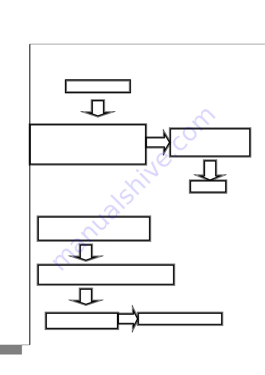
background image


62


AUTO-LENSMETER 

4.3. LCD 

TEST 


z


Measurement screen is not displayed


z


LCD is black-colored and screen is too dimmed


Check1.    SMPS TEST 

Y

E

S

Check1.    LCD is bright but there is no character 

or figure. 

Check2.    There are horizontal lines on LCD and 

  screen display is malfunctioned. 

Check if J12 connector of LCD is

  connected correctly to MAIN 

  BOARD.   

YES

YES

Change LCD

Check1.    Control by turning Bright Volume 

  right and left. 

Check1.    Check if J13 connector of KEYPAD PCB ASS

  is connected correctly. 

Y

E

S

Y

E

S

Change KEYPAD PCB ASS

NO

Change MAIN BOARD PCB ASS

Summary of Contents for CLM-4000

Page 1: ......

Page 2: ...Auto Lensmeter CLM 4000 1 Service Manual Auto Lensmeter CLM 4000...

Page 3: ...20 2 8 HOW TO SET THE RIGHT LEFT SWITCHING POSITION OF PD 21 2 9 DIOPTER SETTING VARIABLES LIST 22 2 10 HOW TO CHANGE THE CCD CAMERA 23 2 11 HOW TO CHANGE THE LED ASSEMBLY 26 2 12 HOW TO CHANGE THE PI...

Page 4: ...CCD CAMERAASSEMBLY 56 3 11 REMOVING SMPS ASSEMBLY AND POWER COVER 58 4 ELECTRICAL SYSTEM 60 4 1 MAIN BOARD PCB ASS Y 60 4 2 INSPECTING SMPS 61 4 3 LCD TEST 62 4 4 LED TEST 63 4 5 UV MODULE TEST 64 4...

Page 5: ...4 AUTO LENSMETER 1 Introduction 1 1 Components List Figure 1 Components Names I...

Page 6: ...Auto Lensmeter CLM 4000 5 Figure 2 Components Names II Figure 3 Components Names III...

Page 7: ...N 1 Examining the Internal Components First 2 Inspecting The value S C A Prism Checking Abnormal State Cleaning the Pinhole Power off and on Checking Abnormal State Setup Again Exit Normal State Norma...

Page 8: ...ns such as diopter and prism It is composed of emitting light part transmit part and receiving light part transmit part composed of collimator lens and 4 pinhole and receiving light part composed of 2...

Page 9: ...ght except the light source z MLA micro lens array Focus the every spot Receiving Light Part z 2 dimentional CMOS sensor converts signals into digital value Emitting light part and receiving light par...

Page 10: ...lens with plus diopter parallel light that has transmitted the collimator lens converges through the measuring lens passes the pinhole and then makes image on CCD On the other hand in case of concave...

Page 11: ...mode While this mode SETUP mark will flicker in the left upper area of the centric circles The booting steps with SETUP mode are as follows A Turn on the power switch Then you can hear the beep sound...

Page 12: ...p STEP into 0 01 In case of prism convert the prism display into P B format Display step STEP and prism display format can be changed in User Setup screen To enter the mentioned User Setup screen pres...

Page 13: ...e as follows A Press the CLEAR button for a while 2 3 seconds B Press the MEASR button for a while C Determine the lens to measure by using two arrow buttons in the left side D Calibrate by using two...

Page 14: ...en press the SAVE QUIT button SAVE SCREEN INFORMATION CEN 398 1073 239 6215 Center of the four points LEN 156 33 Average distance between the center of the four points and the four points CON 1 00 1 0...

Page 15: ...pear and the prism X and Y become 0 C Press the CLEAR button for a while D Press the MEASR button E Using the two arrow buttons in the left side set the diopter to the value of the lens to measure F G...

Page 16: ...Auto Lensmeter CLM 4000 15 The information displayed in the Setting Diopter screen is the same as that of Setting 0D screen After finishing setting up 12 lenses press the CNCT button for 2 seconds...

Page 17: ...place it on the lens cap Especially you should place it NOW PRISM BASE 270 G Press the CAL button and check if DISTANCE value is changed H After selecting the 10 lens from the standard lens set place...

Page 18: ...n press the D SUN button to store some information F Rotate it to become the Base value increase by the 22 or 23 deg G Then press the D SUN button to store some information H Repeat From Step F to Ste...

Page 19: ...ld be halted during the next procedures The marked spots could be checked through the printed out data Prism Base 1st 1 2nd 22 or 23 3rd 45 4th 67 or 68 5th 90 6th 112 or 113 7th 135 8th 157 or 158 9t...

Page 20: ...ts is shown in the below table At every time you can see the recorded information through the thermal printer D After recording the information of 10 spots by pressing TRNS button finally press the TR...

Page 21: ...ures are as followings A Place the rectangular cylindrical lens on the lens cap B Locate it to the center while cling it to the lens table like the following picture C Press the MODE button to go into...

Page 22: ...center of the lens cap And remember the encoder value at the moment E By using the right and left arrow you should make the encoder value of the first row become the very thing at the switching point...

Page 23: ...1 00 1 00 1 00 1 00 average distance and distance rates between the four points and 20D 5th L 166 53 1 00 1 00 1 00 1 00 average distance and distance rates between the four points and 2 5D 6th L 156...

Page 24: ...are as followings A Remove all subassemblies that are the side cover the lens table and the lower cover and the CCD cover etc B Loose the Base Screw I and then take out the old CCD assembly C Detach t...

Page 25: ...CCD parallel with the plane of that of the Base metal as much as you can While two conditions both are all right fasten two CCD Screws J If the sum of two A12 values in 6th row is greater than 0 1 lo...

Page 26: ...Auto Lensmeter CLM 4000 25 Center Point A12 Angle of two points...

Page 27: ...LED assembly The procedures for changing the upper frame Assembly are as followings A Remove the Side Cover Front Upper Cover and Upper Frame B Place the new Upper Frame and fasten it C Assemble the...

Page 28: ...et Set Screws E Lift up the Pinhole Housing and replace it the new one F Turn on the machine to the Setup Mode and then press CLEAR button for a while to go into the Calibration Display G Press the fi...

Page 29: ...28 AUTO LENSMETER 3 Repair Standard 3 1 Removing side cover assembly P I c t u r e 1 2 3 4 5...

Page 30: ...xt separate Knob pin 2 unscrewing two M2 6X8L Remove six screws at the back cover and then separate all screws at the bottom frame Next remove 4 round head screws at Cnnt bracket in Body side cover an...

Page 31: ...30 AUTO LENSMETER 3 2 Removing front cover Upper ass y P I c t u r e 1 2 3 4 5 6 7 8...

Page 32: ...e Body front cover Upper And then separate the Button 5 and the Brightness knob 6 and the Pcb cover and Button Pcb 4 Remove the Membrane switch from the Body front cover through unscrewing M2X6L screw...

Page 33: ...32 AUTO LENSMETER 3 3 Removing Printer ass y P I c t u r e 1 2 3 4 5 6...

Page 34: ...case with unscrewing M2X5L screws Remove the M2 tappng screws and separate the Printer PCB and the Printer case Separate the Printer cover and the Printer case and take out the Printer paper 4 and the...

Page 35: ...34 AUTO LENSMETER 3 4 Removing PD assembly P I c t u r e 1 2 3 4 5 6 7 8 9 10...

Page 36: ...and separate the PD main connector 4 Pull to take out the PD shaft1 keeping the orientation 20deg clockwise rotated And then separate the PD shaft2 the Connect 5 6 and the PD assembly Separate the Ink...

Page 37: ...36 AUTO LENSMETER 3 4 1 Removing PD subassembly P I c t u r e 7 4 8 5 6 2 18 20 17 1 9 13 12 11 10 3 14 15 16 19 21...

Page 38: ...dish head screws and pull out the Nose shaft 5 and separate parts No 6 7 8 sequencially Separate the PD frame through removing the M3X6L dish head screws and remove the Right left PD connector 13 and...

Page 39: ...38 AUTO LENSMETER 3 5 Removing Body front cover Lower ass y P I c t u r e 1 2 3...

Page 40: ...al method 1 Filter cover 2 Filter cover Upper 3 UV cover 4 5 6 7 8 9 10 11 12 13 14 15 16 17 18 19 20 21 Remove the Filter cover 2 the Filter cover Upper and the UV cover from the Body side cover Asse...

Page 41: ...40 AUTO LENSMETER 3 6 Removing UV assembly P I c t u r e 1 2 3 4 5...

Page 42: ...4 UV teflon Upper 5 UV rec 6 7 8 Separate the UV cover Lower 1 from the Frame support UV through removing four M3X5L screws And then separate the UV LED 3 UV teflon 4 UV rec 5 Be careful not to bend t...

Page 43: ...42 AUTO LENSMETER 3 7 Removing Movement assembly P I c t u r e 1 2...

Page 44: ...CLM 4000 43 No Component Removal method 1 Movement Left Assembly 2 Movement Right Assembly 3 4 5 Remove the Movement Left Assembly 1 and the Movement Right Assembly 2 Assembly is the reverse procedure...

Page 45: ...44 AUTO LENSMETER 3 7 1 Removing Movement Left Subassembly P I c t u r e...

Page 46: ...13 CONTROL POSITION FOOT 14 M STS 15 M3X10L 16 F T2 CONTROL POS PIN 17 M3X6L 18 F T2 M FOOT FRAME 19 M3X10L 20 FIXING BRK T ASSY 21 LM BRK T ASSY 1 22 Separate the number 12 through removing the numbe...

Page 47: ...46 AUTO LENSMETER 3 7 2 Removing Movement Right Subassembly P I c t u r e...

Page 48: ...F T2 M PEN FRAME 13 PCB Support 5L 14 PEN EXTENTION SPRING 15 M3X6L 16 M3X6L 17 M3X8L 18 PEN CONT SUPPT 06 02 19 F PEN STOPPER 3 20 M3X8L 21 22 Separate the number 13 14 15 16 Separate the number 10 1...

Page 49: ...48 AUTO LENSMETER 3 8 Removing Gear assembly P I c t u r e 1 2 3 4 5 6 7 8...

Page 50: ...1 from Back bone through removing M3X8L screws Remove the Shaft holder by wrench for M3 Set screw Separate the Gear nut 3 Band washer 4 Teflon washer 5 Teflon washer 6 Gear shaft 7 and Gear 8 Next sep...

Page 51: ...50 AUTO LENSMETER 3 9 Removing Main board assembly P I c t u r e 1 2...

Page 52: ...000 51 No Component Removal method 1 Main board 2 PCB support 3 4 5 Remove the Main board from Frame through unscrewing four M3X5L screws Remove four PCB supports at Frame Assembly is the reverse proc...

Page 53: ...52 AUTO LENSMETER 3 10 Removing Back bone assembly P I c t u r e 1 2 3...

Page 54: ...bone stopper 3 Back bone space 4 5 6 7 First separate the Back bone 1 and Frame through removing four M3X8L screws Separate the Back bone stopper 2 and Back bone through removing M4X8L screws And rem...

Page 55: ...54 AUTO LENSMETER 3 10 1 Removing Lens housing bone and LED subassembly P I c t u r e 1 2 3 4 5 6 7 8...

Page 56: ...ll lens 9 10 Separate the Lens housing bone and Back bone through removing 4 M3X8L screws Remove the Lens housing bone retainer 3 the CCD lens 2 Separate the LED housing and Lens housing bone through...

Page 57: ...56 AUTO LENSMETER 3 10 2 Removing CCD Camera assembly P I c t u r e 1 2 3 4 5 6 7...

Page 58: ...Back bone through removing M3 Set screws Next take apart the 4 Pin hole from the Filter housing Separate the CCD holder 5 and Back bone and remove the CCD holder and CCD camera PCB ass y in sequence...

Page 59: ...58 AUTO LENSMETER 3 11 Removing SMPS Assembly and Power cover P I c t u r e 1 2 3 4 5 6...

Page 60: ...me through removing four M3X6L screws Remove the Power socket 3 through unscrewing two M3X5L screws Separate the Power cover bracket 5 and the Frame and Frame support UV 4 through removing four M3X5L...

Page 61: ...2P 1 4 P text ROM CPU EEP ROM JP2 JP3 J3 THERMAL PRINTER J7 UV SEN IN J8 UV LED OUT J11 DC POWER J13 LCD CCFL J14 RS232 J15 OPTIC LED J16 KEYPAD J17 CCD OUT J18 CCD MTSC J19 CCD J12 LCD DATA J10 MEM...

Page 62: ...Check2 Check the voltage of DC POWER Cable with DMM It should be AC100 or 220V REFERENCE ELECTRICAL CONSTRUCTION DIAGRAM Check1 Check BUZZER beeps after 2 seconds when you turn on the power switch MOD...

Page 63: ...character or figure Check2 There are horizontal lines on LCD and screen display is malfunctioned Check if J12 connector of LCD is connected correctly to MAIN BOARD YES YES Change LCD Check1 Control by...

Page 64: ...ross mark isn t displayed in measurement waiting state Y E S Check1 Place white paper on FILTER COVER and check if circular red right comes out from it Change LED module NO Check1 Change MAIN BOARD PC...

Page 65: ...C LED comes out from UV measurement part NO Change UV LED PCB ASS Y Check1 Check if UV SENSER in UV measurement part is hidden by obstacles such as FILTER COVER N O Check1 Turn on the power switch and...

Page 66: ...nter of PD NO Change MAIN Change PD MODULE Y E S Check1 Check that PD LEVER is in initial position before you turn the power switch Y E S Check1 First turn off the POWER switch and place PD LEVER in i...

Page 67: ...properly Check1 Open PRINTER COVER and check if HEADER LEVER towards upside Check1 Open PRINTER COVER Check2 Check PRINTER PAPER tray Check3 Fill up PRINTER PAPER if PRINTER PAPER is empty or near em...

Page 68: ...there is PC with Windows operating system and serial cable connected to the Lensmeter with simple process about 5 to 10 minutes he she can upgrade the performance of his her Lensmeter without sending...

Page 69: ...two files the executable file dnw exe the configuration file dnw ini It is no need to install it in your desktop computer Therefore just copy the files to the specified directory B Execute the DNW app...

Page 70: ...F Turn on the machine according to the specified method It should be started as the download mode In CLM machine turn on it while pressing the first and the fourth buttons In MRK machine turn on it wh...

Page 71: ...procedure 7 you ll see some information on the terminal and finally you can see the prompt such as STATUS I Click the Transmit item in the Serial Port menu And then choose the OS program file Generall...

Page 72: ...it might be changed according to the type and model of the machine J After finishing the procedure 9 you ll see some information on the terminal and finally you can see the message as following Flash...

Reviews: