F1.49
Part. N. 8000 H4704 (07-2010)
88
91
89
90
ENGINE OVERHAUL
a.
Check that protrusion "a" on clutch control lever "1 " is aligned
to reference "b" on the crankcase as shown in the figure, by
manually pushing the clutch control lever in "c" direction until it
stops.
b.
If protrusion "a" is not aligned to reference "b", align it as fol
-
lows:
• Slacken the check nut "2".
• With clutch control lever completely pressed in "c" direction,
turn short clutch pushrod "3" towards the inside or the outside
until reference "a" is aligned to reference "b".
• Stop the short clutch pushrod to avoid its movement then tighten
the check nut as specified. (see fig. 88)
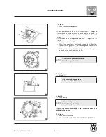
10. Install:
• Oil seal "1"
11. Install:
• Clutch casing
• Tighten the clutch cover bolts in the correct sequence as
shown in the figure.
12. Adjust:
• Clutch cable clearance
• Refer to "CLUTCH CABLE CLEARANCE ADJUSTMENT".
Clutch casing bolt
•
10 Nm (1.0 mkg, 7.2 ft-lb)
Oil seal mounting depth "a"
•
1.4-1.9 mm (0.055-0.075 in)
short clutch pushrod check nut
•
8 Nm (0.8 mkg, 5.8 ft-lb)
9. Adjust:
• Clutch mechanism clearance
Summary of Contents for SMS4
Page 1: ...Workshop Manual TE 125 2011 SMS4 2011 Part N 8000H4704 07 2010 ...
Page 6: ......
Page 7: ...A 1 A Part N 8000 H4704 07 2010 GENERAL INFORMATION Section ...
Page 14: ......
Page 15: ...b 1 Part N 8000 H4704 07 2010 b IMPORTANT NOTICES Section ...
Page 17: ...F 1 Part N 8000 H4704 07 2010 TECHNICAL DATA F Section ...
Page 35: ......
Page 36: ......
Page 37: ...F1 1 Part N 8000 H4704 07 2010 F1 ENGINE OVERHAUL Section ...
Page 109: ...F2 1 Part N 8000 H4704 07 2010 F2 MAINTENANCE Section ...
Page 121: ...F3 1 Part N 8000 H4704 07 2010 F3 ENGINE COOLING Section ...
Page 131: ...F4 1 Part N 8000 H4704 07 2010 F4 CARBURETTOR Section ...
Page 132: ...F4 2 Part N 8000 H4704 07 2010 CARBURETTOR CARBURETTOR ...


