background image

F.13

Part. N. 8000 H4704 (07-2010)

16

17

18

19

B

A

TECHNICAL DATA

Generator cover tightening sequence:

Clutch casing tightening sequence:

Crankcase tightening sequence:

A.

 Left crankcase

B.

 Right crankcase

Summary of Contents for SMS4

Page 1: ...Workshop Manual TE 125 2011 SMS4 2011 Part N 8000H4704 07 2010 ...

Page 2: ... any errors or omissions in this manual and reserves the right to make changes to reflect on going product development Illustrations in the ma nual may differ from actual components No reproduction in full or in part without written authorisation 1st edition 07 2010 ...

Page 3: ... COVERED from serial number onwards Copyright by HUSQVARNA MOTORCYCLES S R L BMW Group Technical Service Via Nino Bixio 8 21024 Varese Italy tel 39 0332 75 61 11 tel 39 0332 756 558 www husqvarna motorcycles com Workshop Manual 1 Chassis serial number TE 125 2011 SMS4 2011 TE 125 ZKHA500AABV000001 SMS 4 ZKHA500ABBV000001 ...

Page 4: ...ion of the problem and ask the appropriate questions to clearly identify problem symptoms diagnose the problem and identify the causes clearly This manual provides basic background information that must be supplemented with the operator s expertise and specific training available through HUSQVARNA held at regular periods plan ahead before starting work gather any spare parts and tools to avoid unn...

Page 5: ...Contents Title Section Foreword table of contents a Important notices b General information A Engine Technical data F Engine overhaul F1 Engine Maintenance F2 Engine cooling F3 Carburettor F4 NOTES Unless otherwise specified data and specifications apply to all models ...

Page 6: ......

Page 7: ...A 1 A Part N 8000 H4704 07 2010 GENERAL INFORMATION Section ...

Page 8: ...3 Timing system A 3 Fuel system A 3 Lubrication A 3 Cooling A 3 Ignition system A 3 Starter A 3 Drive and Transmission A 3 Chassis A 4 Suspension A 4 Brakes A 4 Wheels A 4 Tyres A 4 Electrical components location A 5 Overall dimensions Weight A 6 Capacities A 7 ...

Page 9: ...with adjustable advance digital control Spark plug type NGK CR8E Spark plug gap 0 027 0 031 In Starting electric Transmission Clutch oil bath multiple disc clutch Transmission 6 gear ratios with constant mesh gears Motion is transmitted from engine to gearbox primary shaft through spur gears Primary drive Drive pinion gear z 24 Clutch ring gear z 73 Transmission ratio 3 042 Transmission ratio 1st ...

Page 10: ...0 Rear Light alloy swingarm with progressive suspension and hydraulic monoshock Spring preload adjustment Wheel travel TE in 11 42 Wheel travel SMS in 11 10 Brakes Front Fixed disc ø 10 24 In With floating calliper Brake pad surface area 16 2 cm2 Separate hydraulic circuit and master cylinder with control on right handlebar Rear Brake pad surface area 16 2 cm2 Separate hydraulic circuit pedal and ...

Page 11: ... unit under the fuel tank Voltage regulator under the fuel tank Spark plug on cylinder head 12V 450W starter motor behind the engine cylinder Solenoid starter on the left of rear chassis The electrical system includes the following elements 12V 6Ah battery under the saddle Turning indicator flasher on left side of rear chassis Relay for electric fan fuel injection system and lights on right side o...

Page 12: ...h 1230 mm 48 43 inch 305 mm 12 01 inch 2235 mm 87 99 inch 930 mm 36 61 inch 1450 mm 57 09 inch TE Part N 8000 H4704 07 2010 GENERAL INFORMATION Max Width Overall dimensions Weight Kerb weight without fuel TE SMS 117 Kg 257 94 lb ...

Page 13: ...E 10W50 1 15 litres 0 3 gal oil change and oil filter replacement 0 95 litres 0 25 gal oil change Front fork oil CASTROL SYNTHETIC FORK OIL 5W Coolant CASTROL MOTORCYCLE COOLANT 1 2 litres 0 32 gal Front brake fluid CASTROL RESPONSE SUPER DOT 4 Rear brake fluid CASTROL RESPONSE SUPER DOT 4 Drive chain lubrication CASTROL CHAIN LUBE RACING Grease lubrication CASTROL LM GREASE 2 Electric contact pro...

Page 14: ......

Page 15: ...b 1 Part N 8000 H4704 07 2010 b IMPORTANT NOTICES Section ...

Page 16: ...nality the client must follow the maintenance programme indicated in Section B by having the required maintenance inspections carried out at authorised HUSQVARNA dealers The cost for changing parts and for the labour necessary in order to comply with the maintenance plan is charged to the Client The warranty becomes NULL AND VOID if the motorcycle is rented Notes Left and right side is determined ...

Page 17: ...F 1 Part N 8000 H4704 07 2010 TECHNICAL DATA F Section ...

Page 18: ...gine F 3 Technical data Electrical system F 9 Technical data Tightening torque figures F 10 Technical data Engine torque figures F 11 Technical data Lubrication points and types of Lubricant F 14 Technical data Diagrams and Tables about the Lubrication System F 16 ...

Page 19: ... When replacing the oil filter 1 00 L 1 06 US qt 0 88 Imp qt Oil filter Type of oil filter Paper Oil pump Type of oil pump Trochoidal Internal rotor external rotor end clearance Below 0 15 mm 0 0059 in Limit 0 23 mm 0 0091 in External rotor oil pump housing clearance 0 13 0 18 mm 0 0051 0 0071 in Limit 0 25 mm 0 0098 in Oil pump housing internal and external rotor clearance 0 06 0 11 mm 0 0024 0 0...

Page 20: ... Model number of links DID SCR 0404SV 96 Tensioning system Automatic Rocker arm rocker arm shaft Rocker arm inside diameter 9 985 10 000 mm 0 3931 0 3937 in Limit 10 015 mm 0 3943 in Rocker arm shaft outside diameter 9 966 9 976 mm 0 3924 0 3928 in Limit 9 941 mm 0 3914 in Rocker arm rocker arm shaft clearance 0 009 0 034 mm 0 0004 0 0013 in Limit 0 074 mm 0 0029 in Valve valve seat valve guide Va...

Page 21: ...0004 0 0015 in Limit 0 080 mm 0 0032 in Exhaust valve stem valve guide clearance 0 025 0 052 mm 0 0010 0 0020 in Limit 0 100 mm 0 0039 in Valve stem offset 0 010 mm 0 0004 in Intake cylinder head valve seat width 0 90 1 10 mm 0 0354 0 0433 in Limit 1 6 mm 0 06 in Exhaust cylinder head valve seat width 0 90 1 10 mm 0 0354 0 0433 in Limit 1 6 mm 0 06 in Valve spring Intake free length 41 71 mm 1 64 ...

Page 22: ...13 mm 0 5513 0 5517 in Limit 14 043 mm 0 5529 in Piston pin outside diameter 13 995 14 000 mm 0 5510 0 5512 in Limit 13 975 mm 0 5502 in Piston pin piston pin bore clearance 0 002 0 018 mm 0 0001 0 0007 in Limit 0 068 mm 0 0027 in Piston ring Upper piston ring Ring type Cylinder Dimensions B x T 0 80 x 1 90 mm 0 03 x 0 07 in Piston ring ends gap when installed 0 10 0 25 mm 0 0039 0 0098 in Limit 0...

Page 23: ...ess 2 90 3 10 mm 0 114 0 122 in Wear limit 2 80 mm 0 1102 in Number of plates 1 piece Friction plate 3 thickness 2 90 3 10 mm 0 114 0 122 in Wear limit 2 80 mm 0 1102 in Number of plates 3 pieces Friction plate 2 thickness 2 90 3 10 mm 0 114 0 122 in Wear limit 2 80 mm 0 1102 in Number of plates 1 piece Clutch plate thickness 1 45 1 75 mm 0 057 0 069 in Number of plates 4 pieces Deformation limit ...

Page 24: ... Input shaft offset limit 0 08 mm 0 0032 in Output shaft offset limit 0 08 mm 0 0032 in Gear selector mechanism Type of gear selector mechanism Gear selector drum and shaft Gear selector fork thickness 5 76 5 89 mm 0 227 0 232 in x 1 Gear selector fork thickness 4 76 4 89 mm 0 187 0 193 in x 2 ...

Page 25: ...000 rpm Stator coil resistance 0 32 0 48 Ω at 20 C 68 F Rectifier regulator Type of regulator Semiconductor short circuit Model manufacturer SH640EA SHINDENGEN Rectified voltage CG 14 1 14 9 V Rectifier capacity DC 25 0 A Withstand voltage 200 0 V Electric starting system System type Constant mesh Starter motor Model manufacturer 3C1 YAMAHA Output power 0 20 kW Rotor winding resistance 0 0315 0 03...

Page 26: ... relevant chapters of this manual To avoid deformations gradually tighten the fasteners in a cross pattern until reaching the specified tightening torque Unless otherwise indicated specified tightening torque figures are intended with clean and dry threading The components must be at ambient temperature A Wrench opening B Thread outside diameter A nut B bolt General torque figures Nm m kg ft lb 10...

Page 27: ...er bolt M6 2 10 Nm 1 0 m kg 7 2 ft lb Sealant Three Bond No 1215 Water pump assembly bolt M6 2 10 Nm 1 0 m kg 7 2 ft lb Water pump assembly bolt M6 1 10 Nm 1 0 m kg 7 2 ft lb Water pump housing cover bolt M6 4 10 Nm 1 0 m kg 7 2 ft lb Impeller shaft retainer bolt M6 2 10 Nm 1 0 m kg 7 2 ft lb Thermostat cover bolt M6 2 10 Nm 1 0 m kg 7 2 ft lb Oil pump assembly screw M5 2 4 Nm 0 4 m kg 2 9 ft lb O...

Page 28: ...lutch hub nut M14 1 70 Nm 7 0 m kg 50 ft lb Sprocket stop bolt M6 2 10 Nm 1 0 m kg 7 2 ft lb Crankcase bearing stop bolt M6 2 7 Nm 0 7 m kg 5 1 ft lb Gear selector drum section screw M6 1 12 Nm 1 2 m kg 8 7 ft lb Stop lever bolt M6 1 10 Nm 1 0 m kg 7 2 ft lb Stator coil bolt M6 3 10 Nm 1 0 m kg 7 2 ft lb Crankshaft position sensor bolt M6 2 10 Nm 1 0 m kg 7 2 ft lb Generator rotor nut M12 1 70 Nm ...

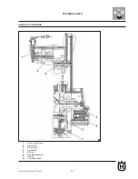
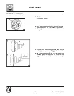
Page 29: ...F 13 Part N 8000 H4704 07 2010 16 17 18 19 B A TECHNICAL DATA Generator cover tightening sequence Clutch casing tightening sequence Crankcase tightening sequence A Left crankcase B Right crankcase ...

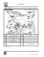
Page 30: ...rocker arm rollers Decompression chamber cam Valve stems and valve stem seals Valve stem tip Rocker arm shafts Rocker arm inside surface Decompression chamber arm joint Engine oil drain plug O ring Oil pump driven gear shaft Oil filter cover O ring Intake manifold O ring Timing mark access screw O ring Crankshaft end access screw O ring Engine oil filler plug O ring Unidirectional starter gear was...

Page 31: ...ver Primary driven gear inner surface Long clutch pushrod Ball and short clutch pushrod Clutch pushrod ball Clutch hub seat and thread Input shaft and sprockets Output shaft and gearwheels Gear selector drum assembly Gear selector forks and their shaft Gearbox shaft Crankshaft position sensor stator assembly cable grommet Sealant Three Bond No 1215 Crankcase mating surfaces Sealant Three Bond No 1...

Page 32: ...Part N 8000 H4707 07 2010 20 TECHNICAL DATA DIAGRAMS AND TABLES ABOUT THE LUBRICATION SYSTEM ENGINE OIL LUBRICATION CHART 1 Oil pump 2 Oil filter element 3 Crankshaft 4 Camshaft 5 Input shaft 6 Output shaft ...

Page 33: ...F 17 Part N 8000 H4704 07 2010 21 TECHNICAL DATA LUBRICATION DIAGRAMS 1 Clutch control lever 2 Input shaft 3 Output shaft 4 Crankshaft 5 Oil filter 6 Oil pump assembly 7 Oil filter A To cylinder head ...

Page 34: ...F 18 Part N 8000 H4707 07 2010 22 TECHNICAL DATA 1 Camshaft 2 Crankshaft 3 Input shaft 4 Output shaft ...

Page 35: ......

Page 36: ......

Page 37: ...F1 1 Part N 8000 H4704 07 2010 F1 ENGINE OVERHAUL Section ...

Page 38: ...1 42 Clutch removal F1 43 Friction plates check F1 43 Clutch plates check F1 44 Clutch springs check F1 44 Clutch housing check F1 45 Clutch hub check F1 45 Pressure plate check F1 45 Clutch control lever and short clutch pushrod check F1 46 Primary drive gear check F1 46 Primary driven gear check F1 46 Clutch installation F1 47 F1 49 Oil pump Oil pump removal F1 50 Oil pump disassembly F1 51 Oil ...

Page 39: ...rankshaft end access screw 1 4 Timing mark access screw 1 5 Engine assembly nut bolt front side 1 1 6 Cylinder head cover 1 7 Cylinder head cover gasket 1 8 Clutch cable support 1 9 Timing chain tensioner 1 10 Timing chain tensioner gasket 1 11 Camshaft sprocket 1 12 Decompression chamber cam 1 13 Cylinder head 1 14 Cylinder head gasket 1 15 Dowel pin 2 New part to be replaced upon reassembly ...

Page 40: ...uen ce Operation Parts to remove Quantity Remarks 16 Timing chain guide exhaust side 1 17 Washer 4 18 Head clamp screw 4 19 Head cover clamp screw 4 Reverse removal procedure to install Cylinder head removal Sealant Three Bond No 1215 New part to be replaced upon reassembly ...

Page 41: ...g 01 a Rotate the crankshaft anticlockwise b With the piston at TDC in compression phase align the reference I c on the camshaft sprocket to reference d on the cylinder head see fig 01 2 Slacken Camshaft sprocket bolt 1 see fig 02 NOTE Holding the generator rotor nut with a wrench 2 slacken the camshaft sprocket bolt 3 Remove Camshaft sprocket NOTE To prevent the timing chain from falling in the c...

Page 42: ...r scratching Spark plug hole threading Valve seats 2 Check Cylinder head Damages scratches Replace Cylinder head water jacket mineral rust deposit Eliminate 3 Measure Cylinder head deformation Not conforming to specifications Surface cylinder head a Place a checking ruler 1 and a feeler gauge 2 transversally on the cylinder head see fig 06 b Measure the deformation c Check if limits are exceeded s...

Page 43: ...ER CHECK 1 Check Timing chain tensioner Clefts damage irregular movement Replace NOTE Pressing the timing chain tensioner rod turn it clockwise with a blade screwdriver b Remove the screwdriver and slowly release the timing chain tensioner rod 1 until stop see fig 08 c Make sure the timing chain tensioner rod is easily removed from the timing chain tensioner slot If the movement is irregular repla...

Page 44: ...haft b Check that the decompression chamber lever 1 moves easily see fig 10 c Without acting on the decompression chamber lever verify that thedecompressionchambercam 2 protrudesfromthecamshaft exhaust cam as shown in figure 11 A d Move the decompression chamber lever 1 in the direction of the arrow and verify that the decompression chamber cam does not protrude from the camshaft exhaust cam as sh...

Page 45: ...et When installing the camshaft sprocket make sure the timing chain is as tight as possible on the exhaust side WARNING Do not rotate the crankshaft during installation of the crankshaft s to avoid damage or an incorrect valve adjustment e Blockingthecamshaft temporarilytightenthecamshaftsprocket bolt f Remove the iron wire from the timing chain a Rotate the crankshaft anticlockwise b Align the re...

Page 46: ... Slightly press with your hands the timing chain tensioner rod and at the same time rotate it completely clockwise with a thin blade screwdriver 1 see fig 14 c Withthetimingchaintensionerrodcompletelyrotatedinthetiming chain tensioner slot with the screwdriver inserted install the timing chain tensioner gasket 2 on the crankcase d Tighten timing chain tensioner bolts 3 to the recommended torque e ...

Page 47: ...erence I on the camshaft sprocket to the statio nary reference d on the cylinder head Misalignment Correct Make reference to installation operations mentioned above Camshaft sprocket bolt 30 Nm 3 0 mkg 22 ft lb WARNING Make sure the camshaft sprocket bolt is tighte ned to the specified torque to avoid the bolt from loosening and damaging the engine 7 Tighten Camshaft sprocket bolt 8 Measure Valve ...

Page 48: ...removal Se quen ce Operation Parts to remove Quantity Remarks Cylinder head 1 Check nut 4 2 Adjuster screw 4 3 Camshaft stop 1 4 Rocker arm shaft 2 5 Intake rocker arm 1 6 Exhaust rocker arm 1 7 Camshaft 1 Reverse removal procedure to install Rocker arms and camshaft removal ...

Page 49: ... blue excessive wear pittings scratches Replace or check lubrication system 3 Measure Rocker arm a inside diameter Not conforming to specifications Replace see fig 18 4 Measure Rocker arm shaft a outside diameter Not conforming to specifications Replace see fig 18 Camshaft lobe dimensions Intake A 30 225 30 325mm 1 1900 1 1939 in Limit 30 125 mm 1 1860 in Intake B 25 114 25 214mm 0 9887 0 9927in L...

Page 50: ...bricant Rocker arm inside surface Molybdenum disulphide oil Rocker arm shaft Engine oil Recommended lubricant Camshaft Molybdenum disulphide oil Camshaft bearing Engine oil 2 Lubricate Camshaft 3 Install Camshaft 1 Make sure the protrusions of the camshaft a and hole b are placed as shown in the figure 4 Install Rocker arms Rocker arm shafts 1 Make sure the crop end a of each rocker arm shaft is f...

Page 51: ...move Quantity Remarks Cylinder head Rocker arms camshaft 1 Valve collet 8 2 Upper spring seat 4 3 Valve spring 4 4 Intake valve 2 5 Exhaust valve 2 6 Valve stem seal 4 7 Lower spring seat 4 8 Valve guide 4 Reverse removal procedure to install Valve and valve spring removal New part to be replaced upon reassembly ...

Page 52: ...lve seal Check valve face valve seat and width of the valve seat a Pour a clean solvent a in the intake and exhaust ports b Check the correct sealing of the valves There should not be any leaks from valve seat 1 2 Remove Valve collets 1 Remove the valve collets compressing the valve spring with the suitable tool 3 Remove Upper spring seat 1 Valve spring 2 Valve 3 Valve stem seal 4 Lower spring sea...

Page 53: ... 0 0004 0 0015 in Limit 0 080 mm 0 0032 in Exhaust valve stem valve guide clearance 0 025 0 052 mm 0 0010 0 0020 in Limit 0 100 mm 0 0039 in 2 Replace Valve guides To facilitate removal and installation of the valve guide and to maintain the correct coupling heat the cylinder head in an oven at 100 C 212 F a Remove the valve guide with a suitable puller 1 see fig 26 b Install the new valve guide w...

Page 54: ... Mushroom shape or diameter greater than the valve stem Replace the valve 5 Measure D valve edge thickness a see fig 29 Not conforming to specifications Replace the valve Intake valve edge thickness D 0 50 0 90 mm 0 0197 0 0354 in Exhaust valve edge thickness D 0 50 0 90 mm 0 0197 0 0354 in Valve stem misalignment 0 010 mm 0 0004 in 6 Measure Valve stem misalignment Not conforming to specification...

Page 55: ...in the cylinder head c Pressthevalvethroughthevalveguideandonthevalveseat so as to leave a clear impression d Measure valve seat width WARNING Do not allow the lapping abrasive agent to pe netrate in the gap between valve stem and valve guide Where the valve seat and valve face have touched Prussian blue is removed 4 Lap Valve face Valve seat After replacing the cylinder head or the valve and valv...

Page 56: ...nd repeat the previous procedures f After each lapping operation remove every trace of lapping abrasive agent from the valve face and valve seat g Apply Prussian blue Dykem b on valve face see fig 36 h Install the valve in the cylinder head i Press the valve through the valve guide and on the valve seat so as to leave a clear impression j Measure width of c valve seat again If the width is not con...

Page 57: ...ng pressure when installed 140 162 N 31 47 36 42 Ibf 14 28 16 52 kgf Intake length when installed 35 30 mm 1 39 in Exhaust length when installed 35 30 mm 1 39 in VALVE SPRINGS CHECK The following procedure is applied to all valve springs 1 Measure Valve spring a free length Not conforming to specifications Replace valve spring see fig 38 2 Measure Compressed valve spring a strength Not conforming ...

Page 58: ...ant see fig 42 3 Install Lower spring seat 1 Valve stem seal 2 Valve 3 Valve spring 4 Upper spring seat 5 in cylinder head see fig 43 Make sure each valve is installed in its original position Install the valve springs with the bigger pitch a facing up wards see fig 44 Recommended lubricant Molybdenum disulphide oil b Smaller pitch New part to be replaced upon reassembly 1 Trim End of the valve st...

Page 59: ...ll Valve collets 1 Install the valve collets compressing the valve spring with the suitable tool 5 To fix the valve collets to the valve stem slightlypatterwitha soft mallet on the end of the valve WARNING If you hit valve tip too hard you could damage the valve ...

Page 60: ...val Se quen ce Operation Parts to remove Quantity Remarks Cylinder head 1 Cylinder 1 2 Cylinder gasket 1 3 Dowel pin 2 4 Piston pin clip 2 5 Piston pin 1 6 Piston 1 7 Upper piston ring 1 8 Lower piston ring 1 9 Scraper ring 1 Reverse removal procedure to install New part to be replaced upon reassembly ...

Page 61: ...ve the piston pin Before removing the piston pin clip cover the opening of the crankcase with a clean cloth to avoid the piston pin clip from falling into the crankcase 2 Remove Upper piston ring Lower piston ring Scraper ring To remove a piston ring widen with your fingers the space between the ends and lift the other side of the piston ring above the piston crown ...

Page 62: ...of D1 or D2 maximum of D5 or D6 R maximum of D1 D3 or D5 minimum of D2 D4 or D 6 Cylinder piston clearance 0 015 0 048 mm 0 0006 0 0019 in Limit 0 15 mm 0 0059 in Piston Diameter D 51 962 51 985 mm 2 0457 2 0466 in b If not conforming to specifications replace the cylinder and replace the piston and piston rings together c Measure D piston skirt a diameter with the micrometer d If not conforming t...

Page 63: ...ngs and their grooves 2 Install Piston ring in the cylinder Level the piston ring in the cylinder with the piston crown 3 Measure Piston ring ends gap Not conforming to specifications Replace piston ring It is not possible to measure the gap between the scraper ring expander spacer ends If the scraper ring gap is excessive replace all three piston rings Piston ring Upper piston ring Piston ring en...

Page 64: ... in Limit 13 975 mm 0 5502 in Piston pin hole inside diameter 14 002 14 013 mm 0 5513 0 5517 in Limit 14 043 mm 0 5529 in 3 Measure Piston pin b hole diameter Not conforming to specifications Replace piston see fig 55 4 Calculate Piston pin piston pin hole clearance Not conforming to specifications Replace the piston and piston pin together Piston pin piston pin hole clearance Piston pin hole b di...

Page 65: ...of the cylinder Before installing the piston pin clips cover the opening of the crankcase with a clean cloth to prevent the clips from falling into the crankcase 3 Lubricate Piston Piston rings Cylinder with recommended lubricant 4 Arrangement of piston ring gaps Piston ring ends gap a Upper piston ring b Upper scraper ring c Scraper ring expander d Lower scraper ring e Lower piston ring f 20 mm 0...

Page 66: ...ntity Remarks Engine oil Sprocket cover 1 Stator coil connector 1 Disconnect 2 2 Crankshaft position sensor connector 1 Disconnect 3 3 Neutral switch cable connector 1 Disconnect 4 Timing mark access screw 1 5 Crankshaft end access screw 1 6 Generator cover 1 7 Generator cover gasket 1 8 Dowel pin 2 9 Crankshaft position sensor 1 New part to be replaced upon reassembly ...

Page 67: ...Remarks 10 Stator coil 1 11 Generator rotor 1 12 Woodruff key 1 13 Unidirectional starter gear 1 14 Bearing 1 15 Washer 1 16 Unidirectional starter idle gear shaft 1 17 Washer 1 18 Snap ring 1 19 Unidirectional starter idle gear 1 20 Unidirectional starter unit 1 Reverse removal procedure to install New part to be replaced upon reassembly ...

Page 68: ...ble tool 3 slacken the generator rotor nut Do not allow the pulley support to touch the protrusion on the generator rotor 2 Remove Generator rotor 1 with flywheel puller 2 Woodruff key Make sure the flywheel puller is centred on the generator rotor UNIDIRECTIONAL STARTER REMOVAL 1 Remove Unidirectional starter bolts 1 see fig 62 Locking out the generator rotor 2 with suitable tool 3 remove unidire...

Page 69: ...r gear 1 on the unidirectional starter and block the generator rotor b When the unidirectional starter gear A is rotated in a clockwise direction itshouldmeshwiththeunidirectionalstarter otherwise the unidirectional starter would be faulty hence to be replaced c When the unidirectional starter gear B is rotated in a counter clockwise direction it should rotate freely otherwise the unidi rectional ...

Page 70: ...way 2 Tighten Generator rotor nut 1 see fig 66 Blocking the generator rotor 2 with suitable tool 3 tighten the generator rotor bolt Do not allow the pulley support to touch the protrusion on the generator rotor 3 Apply Sealant on the rubber block of the crankshaft position sensor stator unit cable 4 Install Generator cover Tighten the generator cover bolts in the correct sequence as shown in the f...

Page 71: ...H4704 07 2010 ENGINE OVERHAUL ELECTRIC STARTING DEVICE Starter motor removal Se quen ce Operation Parts to remove Quantity Remarks 1 Starter motor 1 2 Starter motor cable 1 Disconnect Reverse removal procedure to install ...

Page 72: ...Operation Parts to remove Quantity Remarks 1 O ring 1 2 Starter motor rear cover 1 3 O ring 1 4 Switch 1 5 Starter motor front cover brush support set 1 6 Brush 2 7 Brush spring 2 Reverse removal procedure to install Starter motor disassembly New part to be replaced upon reassembly ...

Page 73: ... 2 resistance Over 1 MΩ 3 Measure Mica a coating Not conforming to specifications Scrape off the mica coating until the correct value with a saw blade appropriately grounded to adapt it to the switch The switch mica coating must be made thin to assure the switch correct operation 4 Measure Resistance of the rotor unit switch and insulation Not conforming to specifications Replace the starter mo to...

Page 74: ... 21 17 oz 400 600 gf 6 Measure Brush spring pressure Not conforming to specifications Replace the brush springs together 7 Check Gear teeth Damage wear Replace the gear 8 Check Bearing Oil seal Damage wear Replace the starter motor front cover brush support set STARTER MOTOR ASSEMBLY 1 Install Starter motor front cover brush support set 1 Starter motor rear cover 2 see fig 73 Align the references ...

Page 75: ...n Parts to remove Quantity Remarks Engine oil Disconnect 1 Clutch cable 1 Disconnect 2 Oil filter element cover 1 3 Oil filter element 1 4 Clutch casing 1 5 Clutch casing gasket 1 6 Dowel pin 2 7 Oil seal 1 Reverse removal procedure to install clutch New part to be replaced upon reassembly ...

Page 76: ...Parts to remove Quantity Remarks 1 Check nut 1 2 Clutch spring 4 3 Pressure plate 1 4 Short clutch pushrod 1 5 Clutch pushrod support 1 6 Ball 1 7 Friction plate 1 1 8 Clutch plate 4 9 Friction plate 3 green 3 10 Friction plate 2 1 Clutch removal New part to be replaced upon reassembly ...

Page 77: ...peration Parts to remove Quantity Remarks 11 Clutch dished plate spring 1 12 Clutch dished plate seat 1 13 Clutch hub nut 1 14 Lock washer 1 15 Clutch hub 1 16 Thrust washer 1 17 Clutch housing 1 18 Spring washer 1 Reverse removal procedure to install New part to be replaced upon reassembly ...

Page 78: ...ver removal Se quen ce Operation Parts to remove Quantity Remarks 1 Clutch control lever 1 2 Clutch control lever spring 1 3 Snap ring 1 4 Oil seal 1 5 Bearing 1 Reverse removal procedure to install Control lever removal New part to be replaced upon reassembly ...

Page 79: ... 3 thickness 2 90 3 10 mm 0 114 0 122 in Wear limit 2 80 mm 0 1102 in Blocking the clutch hub 2 with suitable tool 3 slacken the clutch hub nut FRICTION PLATE CHECK The following procedure applies to all friction plates 1 Check Friction plate Damage wear Replace friction plates together 2 Measure Friction plate thickness Not conforming to specifications Replace friction plates together Measure the...

Page 80: ...to specifications Replace clutch plates together see fig 77 HAS25140 CLUTCH SPRING CHECK The following procedure is applied to all clutch springs 1 Check Clutch spring Damage Replace the clutch springs together 2 Measure Spring a free length Not conforming to specifications Replace the clutch springs together see fig 78 Clutch plate thickness 1 45 1 75 mm 0 057 0 069 in Deformation limit 0 20 mm 0...

Page 81: ... The presence of pittings on clutch housing teeth will cause erratic clutch operation 2 Check Bearing Damage wear Replace bearing seat and clutch housing CLUTCH HUB CHECK 1 Check Spline clutch hub Damage pittings wear Replace the clutch hub see fig 80 The presence of pittings on clutch hub spline will cause erratic clutch operation PRESSURE PLATE CHECK 1 Check Pressure plate Cracks Damage Replace ...

Page 82: ...EAR 2 Check Primary drive gear Damage wear Replace primary drive gear and clutch hou sing together Excessive noise during operation Replace primary drive gear and clutch housing together 3 Install Primary drive gear Refer to BALANCE SHAFT GEAR PRIMARY DRIVEN GEAR CHECK 1 Check Primary driven gear 1 Damage wear Replace primary drive gear and clutch hou sing together Excessive noise during operation...

Page 83: ... 3 Install Clutch hub 1 Lock washer 2 Clutch hub nut Lubricate clutch hub nut threading and lock washer surface with engine oil Align notch a in lock washer with a thread b on the clutch hub 4 Tighten Clutch hub nut 1 Locking the clutch hub 2 with suitable tool 3 tighten the clutch hub nut Clutch hub nut 70 Nm 7 0 mkg 50 ft lb 5 Bend the lock washer tab on one of the flat sides of the nut 6 Lubric...

Page 84: ...g 86 Install the clutch dished plate seat and the clutch dished plate as shown in the figure First of all install a friction plate then alternate a plate and a friction plate 8 Install Pressure plate Clutch springs Clutch spring bolts 1 see fig 87 Gradually tighten the clutch spring bolts in a crossed man ner Recommended lubricant Engine oil Clutch spring bolt 12 Nm 1 2 mkg 8 7 ft lb ...

Page 85: ...ection turn short clutch pushrod 3 towards the inside or the outside until reference a is aligned to reference b Stop the short clutch pushrod to avoid its movement then tighten the check nut as specified see fig 88 10 Install Oil seal 1 11 Install Clutch casing Tighten the clutch cover bolts in the correct sequence as shown in the figure 12 Adjust Clutch cable clearance Refer to CLUTCH CABLE CLEA...

Page 86: ...NGINE OVERHAUL OIL PUMP Oil pump removal Se quen ce Operation Parts to remove Quantity Remarks Clutch housing Balance shaft drive gear 1 Oil baffle plate 1 2 Oil pump unit 1 3 Oil pump drive gear 1 Reverse removal procedure to install ...

Page 87: ... disassembly Se quen ce Operation Parts to remove Quantity Remarks 1 Oil pump housing cover 1 2 Pin 1 3 Oil pump driven gear 1 4 Oil pump inside rotor 1 5 Oil pump outside rotor 1 6 Oil pump housing 1 Reverse removal procedure to install OIL PUMP DISASSEMBLY ...

Page 88: ...Oil pump operation Difficult movement Repeat operations 1 and 2 or replace faulty part s OIL PUMP ASSEMBLY 1 Lubricate Oil pump inside rotor Oil pump outside rotor Oil pump driven gear with recommended lubricant 2 Install Oil pump outside rotor Oil pump inside rotor 1 Oil pump driven gear Pin 2 Inside rotor outside rotor end clearance Below 0 15 mm 0 0059 in Limit 0 23 mm 0 0091 in Outside rotor o...

Page 89: ...pin 2 of the oil pump shaft with groove a of inside rotor 1 3 Check Oil pump operation Refer to OIL PUMP CHECK OIL PUMP INSTALLATION 1 Install Oil pump assembly WARNING Tighten the screws then ensure the oil pump turns smoothly Oil pump unit screw 4 Nm 0 4 mkg 2 9 ft lb OIL PUMP ASSEMBLY ...

Page 90: ...er removal Se quen ce Operation Parts to remove Quantity Remarks Clutch housing Gearbox transmission link 1 Gearbox shaft 1 2 Snap ring 1 3 Gearbox shaft spring 1 4 Stop lever 1 5 Stop lever spring 1 6 Oil seal 1 Reverse removal procedure to install New part to be replaced upon reassembly ...

Page 91: ...tation Replace stop lever Stop lever spring Damage wear Replace GEARBOX SHAFT INSTALLATION 1 Install Stop lever 1 Stop lever spring 2 see fig 95 Install stop lever spring as shown in the figure Engage the ends of the stop lever spring to the stop lever and to the crankcase hub 3 Engage the stop lever with the gear selector drum section unit 2 Install Gearbox shaft 1 Hook the ends of the gearbox sh...

Page 92: ...ntity Remarks Clutch housing 1 Primary drive gear nut 1 2 Balance shaft driven gear nut 1 3 Washer 1 4 Primary drive gear 1 5 Balance shaft drive gear 1 6 Straight key 1 7 Lock washer 1 8 Balance shaft driven gear 1 9 Straight key 1 10 Spacer 1 Reverse removal procedure to install balance shaft gear New part to be replaced upon reassembly ...

Page 93: ...ven gear 3 then slacken the primary drive gear nut 2 Unbend the lock washer tab 3 Slacken Balance shaft driven gear nut 1 Place the aluminium plate a between the balance shaft drive gear 2 and the balance shaft driven gear 3 then slacken the balance shaft driven gear nut 1 Check Balance shaft drive gear Balance shaft driven gear Clefts damage wear Replace 2 Check Primary drive gear PRIMARY DRIVE G...

Page 94: ...lling the washer so that the sharp side c is facing towards the primary drive gear 2 Tighten Balance shaft driven gear nut 1 Primary drive gear nut 2 Place the aluminium plate a between the balance shaft drive gear 3 and the balance shaft driven gear 4 then tighten the balance shaft driven gear nut Place the aluminium plate b between the balance shaft drive gear 3 and the balance shaft driven gear...

Page 95: ... quen ce Operation Parts to remove Quantity Remarks Engine Cylinder head Cylinder Piston Clutch housing Oil pump unit Gearbox shaft Starter motor Balance shaft gears 1 Generator rotor 1 Reverse removal procedure to install crankcase New part to be replaced upon reassembly ...

Page 96: ...arts to remove Quantity Remarks 2 Chain cover 1 3 Timing chain 1 4 Oil drain plug 1 5 Spring 1 6 Engine oil filter 1 7 Neutral switch 1 8 Snap ring 2 9 Spacer 1 10 Right crankcase 1 11 Dowel pin 2 12 Left crankcase 1 Reverse removal procedure to install New part to be replaced upon reassembly ...

Page 97: ... 07 2010 ENGINE OVERHAUL Bearings and oil seal removal Se quen ce Operation Parts to remove Quantity Remarks Crankshaft Balance shaft Transmission 1 Oil seal 1 2 Bearing stop 1 3 Bearing 7 Reverse removal procedure to install ...

Page 98: ...touch the crankcase during crankcase separation 3 Remove Right crankcase CRANKCASE CHECK 1 Accurately wash the crankcase halves with a delicate sol vent 2 Accurately wash the gaskets surface and the crankcase mating surfaces 3 Check Crankcase Cracks Damage Replace Oil galleries Obstruction Blow clean with a compressed air jet WARNING Tap with a mallet on crankcase side Only tap on the crankcase re...

Page 99: ... chain and the camshaft sprocket together 2 Check Timing chain guide intake side Damage wear Replace OIL FILTER CHECK 1 Check Oil filter Damage Replace Contamination Clean with a solvent BEARINGS AND OIL SEAL CHECK 1 Check Bearings Clean and lubricate the bearings then manually rotate the inner race Hard movement Replace Oil seal Damage wear Replace ...

Page 100: ... a facing outside Apply the threadlock LOCTITE on the bearing stop bolt threadings CRANKCASE ASSEMBLY 1 Accurately wash all gaskets and crankcase mating surfa ces 2 Apply Sealant on crankcase mating surface Avoid sealant from contacting oil channels 3 Install Right crankcase Rotate the gear selector drum section 1 to the position shown in the figure In this position the gear selector drum section ...

Page 101: ...0 H4704 07 2010 109 ENGINE OVERHAUL Gradually tighten each bolt of 1 4 turn at the time as indicated in the sequence A Left crankcase B Right crankcase CRANKCASE ASSEMBLY M6x70 mm 7 9 11 M6x55 mm 14 15 M6x45 mm 1 5 10 ...

Page 102: ...F1 66 Part N 8000 H4704 07 2010 ENGINE OVERHAUL Se quen ce Operation Parts to remove Quantity Remarks Crankcase 1 Balance shaft 1 2 Crankshaft 1 crankshaft New part to be replaced upon reassembly ...

Page 103: ...place crankshaft 3 Measure Crankshaft width Not conforming to specifications Replace crankshaft Offset limit C 0 030 mm 0 0012 in 4 Check Crankshaft sprocket Damage wear Replace the crankshaft Bearing Cracks damage wear Replace the crankshaft 5 Check Crankshaft pin Scratches wear Replace the crankshaft Crankshaft pin oil gallery Obstruction Blow clean with a compressed air jet Connecting rod big e...

Page 104: ... Operation Parts to remove Quantity Remarks Crankcase 1 Gearbox fork shaft 1 2 Spring 2 3 Gear selector drum assembly 1 4 Gear selector fork R 1 5 Gear selector fork C 1 6 Gear selector fork L 1 7 Output shaft assembly 1 8 Complete input shaft 1 9 Long clutch pushrod 1 Reverse removal procedure to install transmission ...

Page 105: ... ce Operation Parts to remove Quantity Remarks 1 Washer 1 2 2nd speed gear 1 3 6th speed gear 1 4 Washer 1 5 1st speed gear 1 6 Spacer 1 7 5th speed gear 1 8 Snap ring 1 9 Safety washer 1 10 4th speed gear 1 11 3rd speed gear 1 12 Output shaft 1 Reverse removal procedure to install ...

Page 106: ... on a flat surface Deformations Replace 3 Check Gear selector fork movement on the gearbox fork shaft Hard movement Replace the gear selector forks and the ge arbox fork shaft together GEAR SELECTOR DRUM UNIT CHECK 1 Check Gear selector drum groove Damage scratches wear Replace the gear selector drum unit Gear selector drum section 1 Damage wear Replace the gear selector drum unit Gear selector dr...

Page 107: ...117 3 Check Transmission gears Discoloured blue pittings wear Replace faulty gear s Transmission gears teeth Cracks damage rounded edges Replace faulty gear s 4 Check Correct gear meshing each sprocket with its gear Not correct Reassemble transmission shaft units 5 Check Transmission gear movement Hard movement Replace faulty part s Output shaft offset limit 0 08 mm 0 0032 in CLUTCH PUSHROD CHECK ...

Page 108: ...primary shaft 2 as shown in the figure GEAR SELECTOR FORKS AND GEAR SELECTOR DRUM UNIT INSTALLATION 1 Install Gear selector fork L 1 Gear selector fork C 2 Gear selector fork R 3 Gear selector drum unit 4 Springs Gearbox fork shaft 5 see fig 121 Reference protrusions on the gear selector forks must face towards the right side of the engine and be in the following sequence R C L 2 Check Transmissio...

Page 109: ...F2 1 Part N 8000 H4704 07 2010 F2 MAINTENANCE Section ...

Page 110: ...nd lubrication F2 3 Maintenance valve clearance adjustment F2 4 Maintenance ignition advance check F2 7 Maintenance measuring compression pressure F2 8 Maintenance engine oil level check F2 9 Maintenance engine oil change F2 10 Maintenance clutch cable clearance adjustment F2 12 ...

Page 111: ... kilometres or in miles for the United Kingdom From 30000 km 17500 mi repeat maintenance intervals starting from operations scheduled for 6000 km 3500 mi Positions highlighted with a star shall be entrusted to a Yamaha dealer since they require special tools specifications and technical skills No Position Check or Maintenance Odometer reading Yearly I n s p e c tion 1000 km 600 mi 6000 km 3500 mi ...

Page 112: ...ylinder head cover gasket Refer to CYLINDER HEAD Remove the cylinder head cover by sliding it off the chassis tubes Remove 2 Timing mark access screw 1 Crankshaft end access screw 2 see fig 01 Measure 3 Valve clearance Valve clearance with cold engine Intake 0 10 0 14 mm 0 0039 0 0055 in Exhaust 0 20 0 24 mm 0 0079 0 0094 in Not conforming to specs Adjust Turn crankshaft counter clockwise a Align ...

Page 113: ...juster screw end and the valve stem tip see fig 05 Turn adjuster screw c 3 in direction a or b until obtaining the specified valve clearance see fig 06 Hold the adjuster screw in place and tighten the check nut as specified Measure valve clearance again d If valve clearance still does not meet the specifications repeat e all valve clearance adjustment steps until obtaining correct clearance Measur...

Page 114: ...m 0 028 0 031 in Disconnect 8 Spark plug cap Remove 9 Spark plug WARNING Before removing the spark plug remove any im purities built up inside its seat with compressed air to avoid they enter the cylinder Check 10 Type of spark plug Incorrect Change Check 11 Electrode 1 Damage wear Change spark plug Insulation 2 Strange colour Change spark plug Normal colour ranges from quite dark reddish brown to...

Page 115: ...f the whole ignition system Ensure all connections are secure and not corroded Remove 1 Timing mark access screw 1 see fig 08 Connect 2 Stroboscopic lamp 1 Digital rev meter see fig 09 Check 3 Ignition advance Start engine warm up a few minutes then let it idle at recom a mended speed Check alignment of stationary reference mark b a on generator cover with TDC reference b onto generator rotor Inco...

Page 116: ...mperature sensor connector 1 Spark plug cap 2 see fig 11 Remove 4 Spark plug Install 5 Extension 1 Compression gauge 2 see fig 12 WARNING Before removing the spark plug remove any impurities built up inside its seat with compres sed air to avoid they enter the cylinder Standard compression pressure at sea level 550 kPa 600 rpm 78 2 psi 600 rpm 5 5 kgf cm2 600 rpm Minimum maximum 480 620 kPa 68 3 8...

Page 117: ... Repair Value equal to the one measured with no oil Piston ring valves and cylinder head or piston probably faulty Repair Remove 7 Extension Compression gauge lnstall 8 Spark plug Connect 9 Spark plug cap Coolant temperature sensor connector ENGINE OIL LEVEL CHECK Set vehicle on a flat surface 1 Position the vehicle on a suitable support Ensure vehicle is upright Start engine warm it up a few minu...

Page 118: ...e fig 15 Start engine warm it up a few minutes then stop it 4 Check engine oil level again 5 Before checking engine oil level allow a few minutes for oil to settle ENGINE OIL CHANGE Start engine warm it up a few minutes then stop it 1 Set a collection tank under oil drain bolt 2 Install 3 Engine oil drain adapter 1 Placed under the rider saddle together with the owner s tool kit see fig 16 Remove ...

Page 119: ...ilter element cover bolt 10 Nm 1 0 mkg 7 2 ft lb Oil filter element cover bolt 10 Nm 1 0 mkg 7 2 ft lb Engine oil capacity Total quantity 1 15 L 1 22 US qt 1 01 Imp qt Without changing oil filter element 0 95 L 1 00 US qt 0 84 Imp qt When changing oil filter element 1 00 L 1 06 US qt 0 88 Imp qt Check d Engine oil filter Dirty Clean Install 7 Engine oil filter Spring O ring New Oil drain plug Fill...

Page 120: ...eizure Check engine oil channels the oil filter element and oil pump for c damage or leaks Refer to OIL PUMP Start engine after fixing the problem and check engine oil pres d sure again Tighten the oil level inspection plug as specified e Oil level inspection plug 7 Nm 0 7 mkg 5 1 ft lb Direction a Clutch cable clearance increases Direction b Clutch cable clearance decreases CLUTCH CABLE CLEARANCE...

Page 121: ...F3 1 Part N 8000 H4704 07 2010 F3 ENGINE COOLING Section ...

Page 122: ...E COOLING Cool thermostat F3 3 Cool water pump F3 4 Cool thermostat check F3 5 Cool thermostat installation F3 6 Cool water pump disassembly F3 7 Cool water pump check F3 8 Cool water pump assembly F3 9 Cool water pump installation F3 10 ...

Page 123: ...emoval Se quen ce Operation Parts to remove Quantity Remarks 1 Coolant temperature sensor connector 1 2 Coolant temperature sensor 1 3 Thermostat cover 1 4 Thermostat 1 5 Radiator inlet hose 1 1 Reverse removal procedure to install New part to be replaced upon reassembly ...

Page 124: ...cessary to remove the water pump unless coolant level is extremely low or coolant contains some engine oil 1 Radiator outlet hose 1 2 Water pump breather hose 1 3 Cylinder head breather hose 1 Disconnect 4 Radiator bolt 1 5 Water pump assembly 1 Reverse removal procedure to install WATER PUMP New part to be replaced upon reassembly ...

Page 125: ...ater Slowly warm up the water b 3 Dip a thermometer c 4 in water Stir water then look at the thermostat and thermometer reading d see fig 02 A Fully closed B Fully open If you have any doubts about thermostat accuracy change it A faulty thermostat could provoke a dangerous overheating or undercooling Check 2 Thermostat cover Cracks damage Replace Check 3 Radiator inlet hose Cracks damage Replace ...

Page 126: ...stall the thermostat with breather hole a facing up see fig 03 Install 2 Copper washer Coolant temperature sensor Coolant temperature sensor 18 Nm 1 8 mkg 13 ft lb WARNING Pay utmost attention when handling the coolant temperature sensor Change any part that has fallen or suffered a strong impact ...

Page 127: ... 1 Water pump housing cover 1 2 Water pump housing cover gasket 1 3 Impeller shaft retainer 1 4 Impeller shaft 1 5 Water pump housing plate 1 6 Water pump housing seal 1 7 Water pump seal 1 8 Bearing 1 9 Water pump housing 1 Reverse removal procedure to install Water pump disassembly New part to be replaced upon reassembly ...

Page 128: ... inside the water pump housing 2 see fig 04 Remove 2 Bearing 1 Remove the bearing from outside the water pump housing 2 see fig 05 WATER PUMP CHECK Check 1 Water pump housing cover Water pump housing Cracks damage Replace Impeller shaft Clefts damage wear Change Bearing Hard movement Replace Radiator outlet hose Cracks damage Replace ...

Page 129: ...ng the special tools and set it at the specified depth as shown Recommended lubricant Lithium soap base grease Impeller shaft retainer bolt 10 Nm 1 0 mkg 7 2 ft lb LOCTITE see fig 06 A Push down 3 Mechanical seal installing tool 4 Centre duct shaft bearing installing tool see fig 07 0 0 5 mm 0 0 02 in a Lubricate 2 Water pump seal lip Install 3 Water pump housing seal 1 Water pump housing plate 2 ...

Page 130: ...ump housing plate and impeller shaft retainer as shown After installation ensure impeller shaft can turn smoothly see fig 08 WATER PUMP INSTALLATION Install 1 Water pump assembly 1 O ring 2 Align projecting part a on impeller shaft to slit b on camshaft sprocket bolt Lubricate the O rings with a thin layer of lithium soap base grease see fig 09 New part to be replaced upon reassembly New part to b...

Page 131: ...F4 1 Part N 8000 H4704 07 2010 F4 CARBURETTOR Section ...

Page 132: ...F4 2 Part N 8000 H4704 07 2010 CARBURETTOR CARBURETTOR ...

Page 133: ...ion Clean a Flush carburettor with a petroleum base solvent Do not use corrosive detergent solutions b Blow all passages and jets with compressed air 3 Check float chamber body Dirty Clean 4 Check floater Damage Replace 5 Check needle valve Damage obstruction wear Change 6 Check piston valve Damage scratches wear Change piston valve diaphragm enricher in release stage diaphragm Clefts tears Change...

Page 134: ... all parts with a petroleum base solvent Always use a new seal CARBURETTOR ASSEMBLY 1 Measure floater height a Not conforming to specs Adjust Floater height A G 17 5 mm 0 69 in a Hold carburettor upside down b Measure the distance from float chamber front mating surface without seal to floater top point NOTE Floater arm should rest onto needle valve without shifting it down c If floater height doe...

Page 135: ...Idle air screw loosened by turns 4 Install accelerator pump assembly 5 Install enricher assembly in release stage CARBURETTOR INSTALLATION 1 Install carburettor NOTE Align protruding part a on carburettor to chamfer b on intake manifold 2 Adjust idle speed Idle speed 1750 50 rpm 3 Adjust accelerator cable clearance ...

Page 136: ...F4 6 Part N 8000 H4704 07 2010 CARBURETTOR ...

Reviews: