F2.4
Part. N. 8000 H4704 (07-2010)
01
02
03
MAINTENANCE
VALVE CLEARANCE ADJUSTMENT
Valve clearance shall be adjusted with cold engine, at ambient
•
temperature.
When measuring or adjusting valve clearance, the piston
•
shall be set at Top Dead Centre (TDC) during the compres-
sion stroke.
The following procedure applies to all valves.
•
Remove:
1.
Cylinder head cover
•
Cylinder head cover gasket.
•
Refer to "CYLINDER HEAD".
Remove the cylinder head cover by sliding it off the chassis
•
tubes.
Remove:
2.
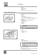
Timing mark access screw "
•
1
".
Crankshaft end access screw "
•
2
". (see fig.01)
Measure:
3.
Valve clearance
•
Valve clearance (with cold engine)
Intake
•
.........
0.10-0.14 mm (0.0039-0.0055 in)
Exhaust
•
.........
0.20-0.24 mm (0.0079-0.0094 in)
Not conforming to specs
Adjust.
Turn crankshaft counter clockwise.
a.
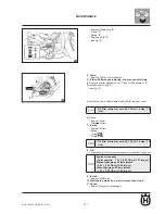
Align TDC reference "
b.
a
" on generator rotor to fixed reference
mark "
b
" onto generator cover. (see fig.02)
Ensure camshaft lobes are positioned as shown. (see fig.03)
c.
Summary of Contents for SMS4
Page 1: ...Workshop Manual TE 125 2011 SMS4 2011 Part N 8000H4704 07 2010 ...
Page 6: ......
Page 7: ...A 1 A Part N 8000 H4704 07 2010 GENERAL INFORMATION Section ...
Page 14: ......
Page 15: ...b 1 Part N 8000 H4704 07 2010 b IMPORTANT NOTICES Section ...
Page 17: ...F 1 Part N 8000 H4704 07 2010 TECHNICAL DATA F Section ...
Page 35: ......
Page 36: ......
Page 37: ...F1 1 Part N 8000 H4704 07 2010 F1 ENGINE OVERHAUL Section ...
Page 109: ...F2 1 Part N 8000 H4704 07 2010 F2 MAINTENANCE Section ...
Page 121: ...F3 1 Part N 8000 H4704 07 2010 F3 ENGINE COOLING Section ...
Page 131: ...F4 1 Part N 8000 H4704 07 2010 F4 CARBURETTOR Section ...
Page 132: ...F4 2 Part N 8000 H4704 07 2010 CARBURETTOR CARBURETTOR ...


