English - 33
Carburettor
15.8 Manifold
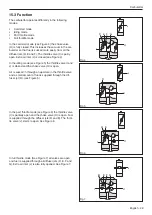
1. Pull the flange (L) off the inlet pipe (J). See Figure
15.
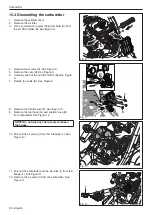
2. Remove the 4 screws. See Figure 16.
3. Remove the insulation wall (K) and inlet pipe (J)
from the cylinder. See Figure 17.
15.9 Assemble on the saw
1. Attach the manifold on the cylinder. See Figure 15
- 17 in the chapter 15.8 Manifold. Make sure to use
the correct torque. See chapter 4 Service data.
2. Hook the air valve (I) to the carburettor as outlined
in Figure 11.
3. Attach the air valve (I) to the inlet pipe (J). See
Figure 11.
4. Fit the carburettor on the flange (L) Figure 11.
5. Attach the throttle wire (F) to the carburettor as
outlined in Figure 10.
6. Attach the fuel hose (G) to the carburettor as out-
lined in Figure 10.
7. Attach the suction hose (H) to the carburettor as
outlined in Figure 10.
8. Attach the ignition cable (E) to the start/stop switch
and fit the air filter holder (B) to the carburettor.
Make sure the hoses coming to the primer bulb
don’t gets pinched. See Figure 9.
9. Attach the primer bulb to the air filter holder.
10. Fit the air filter to the air filter holder.
11. Attach the cylinder cover.
Fig. 15
Fig. 16
Fig. 17
J
L
K
J


