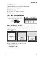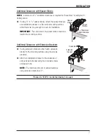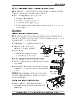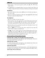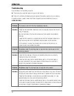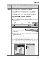
INSTALLATION
4
Mount the Installation Brackets — Inside Mount
■
■
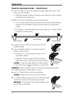
Mark 2" from each jamb for bracket location.
■
➤
If more than two installation brackets came with your order, space additional bracket(s)
between the two end brackets and mark their location. Mount into wood whenever
possible.
■
➤
For PowerView
™
shadings with battery wand, allow a minimum of 17" between bracket
centerlines for the battery wand.
■
■
Determine whether or not to remove one or both tabs from the installation brackets.
■
➤
If using the optional back cover, use pliers to remove both tabs
from the installation brackets.
■
➤
For PowerView shadings with battery wand without a back cover,
leave both tabs on the brackets. The top tab helps ensure that
there is clearance for the wand.
■
➤
For all other shadings without a back cover, use pliers to remove the top tab only.
■
➤
Save any removed top tabs for use as shims when needed.
■
■
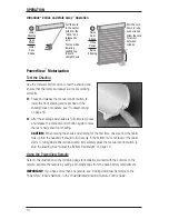
Review the minimum depth requirements in the table below.
■
■
Center the installation brackets on your marks and mark the location of the screw holes.
■
➤
Allow sufficient rear clearance when positioning the brackets. With no back cover, the
bottom tab provides the necessary clearance (
1
/
4
") for all systems except PowerView
with battery wand, which requires
7
/
8
" rear clearance. (Rear clearance is the distance
between the back of the installation bracket and the glass or frame.) Add an extra
1
/
4
" of
rear clearance if the optional back cover is used.
■
➤
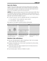
After positioning the bracket, determine whether the front or
rear set of bracket holes is closer to the center of the casement.
Mark the location of the correct pair of holes.
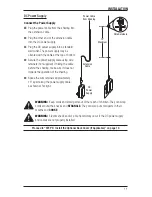
Window Opening
2"
2"
Operating System Type
Minimum Mounting Depth
Fully Recessed Depth
No Back Cover
With Back Cover
No Back Cover
With Back Cover
PowerView with Battery Wand
1
3
/
4
"
2"
4
5
/
16
"
4
9
/
16
"
All Other Systems
1"
1
1
/
4
"
3
13
/
16
"
4
1
/
16
"
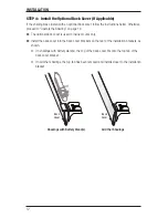
Top
Tab
Bottom
Tab

