Documents and Forms
2.7
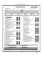
____ Co detectors operatonal
____ engne compartment blower operatonal
____ Auto fire suppression system operational
(engne compartment)
____ Shore power cord and adapter plug operatonal.
(
See manufacturer’s manual for complete detals.)
____ 110 or 220 VAC outlets operatonal - ground fault crcuts functonng
____ 110 or 220 VAC nverter/battery chargng systems functonng properly
Fresh Water Systems
____ hot water heater dran shut
____ All spgots and hose bbs shut
____ All tank(s) flushed clean and free of debris and antifreeze
____ Water heater tank and lines flushed of antifreeze
____ All water lnes and components purged of ar and checked for leaks
____ Sinks and drains checked for leaks and adequate flow
____ Cockpt shower operatonal
____ Fresh water filters clean
____ Tank water level ndcator systems operatng- labelng and tank valve selecton correspond
Head and Holding Tank Systems
____ Vent clear from tank to atmosphere
____ Flled wth fresh water (electrc head)
____ Toilets flush to holding tanks properly
____ Waste level ndcatng system properly functonng
____ No leaks at any hose fitting within the system
Galley Systems
____ Stovetop or oven operatonal
(Refer to manufacturer’s manual for proper operaton and trouble shootng.)
____ Gmbal latch secure and operatonal
____ Mcrowave operatonal
____ Refrgerator operatonal and proper temperature attaned
____ Freezer operatonal and proper temperature attaned
____ Icebox drans properly
____ Icebox dran plugs nstalled
____ USCG waste dsposal-warnng poster onboard or n owner’s package
____ LPG tank filled, installed and connected to regulator; inspect Gas system for leaks after 3 minutes
(Should a leak be detected mmedately close the man valve ext boat and seek professonal assstance for a
thorough nspecton.)
____ lPG storage locker dran open and tank storage area free of debrs
Topside Inspection
____ Swm platform operates properly
____ Cockpt cushons cleaned and nstalled
____ Canvas properly cleaned and nstalled
____ Rubral properly secured to hull
____ load bearng hardware securely fastened; ths ncludes but s not lmted to cleats and handrals
____ Lifeline fittings tight and secure
____ Sldng hatch drans free of debrs
Summary of Contents for MH37
Page 1: ...V1 R02_110714 Operator s Manual MH37 MARLOW HUNTER LLC ...
Page 2: ......
Page 11: ...Introduction Chapter 1 MH37 MARLOW HUNTER LLC V1 R02_110714 ...
Page 12: ...Introduction This Page Intentionally Left Blank ...
Page 17: ...Introduction 1 5 Notes ...
Page 18: ...Introduction 1 6 Notes ...
Page 19: ...Documents Forms Chapter 2 MH37 MARLOW HUNTER LLC and V1 R02_110714 ...
Page 20: ...Documents and Forms This Page Intentionally Left Blank ...
Page 44: ...Documents and Forms 2 24 Power Squadron recommendat ons for ma ntenance and safe boat ng ...
Page 46: ...Documents and Forms 2 26 Dates of pract ce dr lls and onboard safety nspect ons ...
Page 47: ...Documents and Forms My personal preferences for ma ntenance tems safety gear 2 27 ...
Page 48: ...Documents and Forms 2 28 Notes ...
Page 49: ...Limited Warranty Chapter 3 MH37 MARLOW HUNTER LLC V1 R02_110714 ...
Page 50: ...This Page Intentionally Left Blank Limited Warranty 3 2 ...
Page 64: ...Limited Warranty 3 16 Notes ...
Page 65: ...Boating Safety Chapter 4 MH37 MARLOW HUNTER LLC V1 R02_110714 ...
Page 66: ...Boating Safety This Page Intentionally Left Blank ...
Page 86: ...Boating Safety 4 20 DECK HARDWARE LAYOUT Figure 4 9 ...
Page 89: ...Boating Safety 4 23 Notes ...
Page 90: ...Boating Safety 4 24 Notes ...
Page 91: ...Fuel Systems Chapter 5 MH37 MARLOW HUNTER LLC V1 R02_110714 ...
Page 92: ...This Page Intentionally Left Blank Fuel Systems ...
Page 102: ...Figure 5 11 FUEL SYSTEM LAYOUT WITH OPTIONAL GENERATOR Fuel Systems 5 10 ...
Page 103: ...LPG SYSTEM LAYOUT Figure 5 12 Fuel Systems 5 11 ...
Page 104: ...Notes Fuel Systems 5 12 ...
Page 105: ...MH37 Underwater Gear Chapter 6 V1 R02_110714 MARLOW HUNTER LLC ...
Page 106: ...Underwater Gear This Page Intentionally Left Blank ...
Page 115: ...Underwater Gear 6 9 INTAKES DISCHARGES BELOW WATERLINE Figure 6 17 ...
Page 117: ...Underwater Gear 6 11 Notes ...
Page 118: ...Underwater Gear 6 12 Notes ...
Page 119: ...DC Electric System Chapter 7 MH37 MARLOW HUNTER LLC V1 R02_110714 ...
Page 120: ...DC Electric Systems This Page Intentionally Left Blank ...
Page 138: ...DC Electric Systems 7 18 DC OUTLET LAYOUT Figure 7 21 ...
Page 139: ...DC Electric Systems 7 19 Notes ...
Page 140: ...DC Electric Systems 7 20 Notes ...
Page 141: ...MARLOW HUNTER LLC MH37 AC Electric System Chapter 8 V1 R02_110714 ...
Page 142: ...AC Electric Systems This Page Intentionally Left Blank ...
Page 154: ...AC Electric Systems 8 12 AC SYSTEM MAJOR COMPONENT GENERAL LAYOUT WITH INVERTER Figure 8 17 ...
Page 156: ...AC Electric Systems 8 14 AIR CONDITIONER DUCTING LAYOUT Figure 8 19 ...
Page 157: ...AC Electric Systems 8 15 Notes ...
Page 158: ...AC Electric Systems 8 16 Notes ...
Page 159: ...MARLOW HUNTER LLC MH37 Water Systems Chapter 9 V1 R02_110714 ...
Page 160: ...Water Systems This Page Intentionally Left Blank ...
Page 168: ...Water Systems 9 8 FRESH WATER SYSTEM LAYOUT Figure 9 14 ...
Page 169: ...Water Systems 9 9 OPTIONAL AIR CONDITIONING PLUMBING LAYOUT Figure 9 15 ...
Page 170: ...Water Systems 9 10 OPTIONAL GENERATOR PLUMBING LAYOUT Figure 9 16 ...
Page 171: ...Water Systems 9 11 MANUAL TOILET RAW WATER HEAT EXCHANGER LAYOUTS Figure 9 17 ...
Page 172: ...Water Systems 9 12 Notes ...
Page 173: ...Waste Systems Chapter 10 MH37 MARLOW HUNTER LLC V1 R02_110714 ...
Page 174: ...Waste and Sanitation Systems This Page Intentionally Left Blank ...
Page 183: ...Waste and Sanitation Systems 10 9 BILGE SUMP PUMP DRAIN SYSTEM LAYOUT Figure 10 17 ...
Page 184: ...Waste and Sanitation Systems 10 10 AIR CONDITIONING WASTE WATER LAYOUT Figure 10 18 ...
Page 187: ...Waste and Sanitation Systems 10 13 Notes ...
Page 188: ...Waste and Sanitation Systems 10 14 Notes ...
Page 189: ...MH37 Engines Transmissions Chapter 11 MARLOW HUNTER LLC and V1 R02_110714 ...
Page 190: ...Engines and Transmissions This Page Intentionally Left Blank ...
Page 192: ...Engines and Transmissions 11 2 Engines and Transmissions 11 2 Figure 11 2 ...
Page 193: ...Engines and Transmissions 11 3 Figure 11 4 ...
Page 201: ...Engines and Transmissions 11 11 Notes ...
Page 202: ...Engines and Transmissions 11 12 Notes ...
Page 203: ...and MARLOW HUNTER LLC MH37 Sails Rigging Chapter 12 V1 R02_110714 ...
Page 204: ...Sails and Rigging This Page Intentionally Left Blank ...
Page 218: ...Sails and Rigging 12 14 Figure 12 14 GENERAL RIG COMPONENTS ...
Page 219: ...Sails and Rigging 12 15 MAINSAIL JIB SPECIFICATIONS Figure 12 15 ...
Page 220: ...Sails and Rigging 12 16 STANDING RIGGING SPECIFICATIONS STANDARD FURLING RIGS Figure 12 16 ...
Page 222: ...Sails and Rigging 12 18 Figure 12 18 RUNNING RIGGING SPECIFICATIONS ...
Page 224: ...Sails and Rigging 12 20 Figure 12 21 MAINSHEET BOOM OUTHAUL LAYOUT ...
Page 226: ...Sails and Rigging 12 22 VANG LAYOUT CONVENTIONAL SOLID Figure 12 23 ...
Page 228: ...Sails and Rigging 12 24 Figure 12 25 SPINNAKER LAYOUT OPTION ...
Page 229: ...Sails and Rigging 12 25 Figure 12 26 GENERALIZED REEFING LAYOUT ...
Page 230: ...Sails and Rigging 12 26 LAZY JACK LAYOUT WITH OPTIONAL STACK PACK SAIL COVER Figure 12 27 ...
Page 231: ...Sails and Rigging 12 27 STACK PACK SAIL COVER INSTALLATION WITH LAZY JACKS Figure 12 28 ...
Page 232: ...Sails and Rigging 12 28 Notes ...
Page 233: ...MH37 Getting Underway Chapter 13 MARLOW HUNTER LLC V1 R02_110714 ...
Page 234: ...Getting Underway This Page Intentionally Left Blank ...
Page 240: ...Getting Underway 13 6 Notes ...
Page 241: ...MH37 Maintenance Chapter 14 MARLOW HUNTER LLC V1 R02_110714 ...
Page 242: ...Maintenance This Page Intentionally Left Blank ...
Page 257: ...Maintenance 14 15 SLING LOCATIONS Figure 14 3 ...
Page 258: ...Maintenance 14 16 Notes ...
Page 259: ...Glossary Chapter 15 MH37 MARLOW HUNTER LLC V1 R02_110714 ...
Page 260: ...Glossary This Page Intentionally Left Blank ...


