


Water Systems
9.1
T
he fresh and raw water systems dscussons wll con-
sst of the followng categores:
Fresh Water Tanks and Flls
Pumps
Pck-ups, Valves and Straners
Water Heater
Please refer to Fgure 9.18 for the overall fresh water
system layout.
9.1 Fresh Water Tanks and Fills
The fresh water system on your boat ncludes two water
tanks wth a 40 US gallon (151.4L) capacty per tank.
Each tank ncludes a water fll fttng (Fg. 9.1), located on
the port and starboard sde decks. Both the port and star-
board tank fll fttngs are located forward of the jb slder
track. Also each tank has a vent fttng (see the Waste
chapter n ths manual for detals on ventng) to allow the
tank to “breathe”. The port tank vent s a thru-hull fttng
located aft of the water fll fttng. The starboard tank vent
s a deck fttng located on the toe-ral near the water fll
fttng (see Boatng Safety and Underwater Gear chapters
of ths manual for the deck hardware and thru-deck loca-
ton dagrams).
The fresh water tanks are located n the man salon. The
port tank can be accessed through the port aft settee bot-
tom panels and/or adjacent floor panes (Fg. 9.2). The
starboard tank can be accessed through the aft dnette
seat bottom panels to the left of the water heater (under
the optonal ar condtoner) (9.3).
Fgure 9.1
9.1.1 To fill the fresh water tanks
Ensure the potable water supply s sutable for drnk-
ng. Not all potable water s drnkng water. Check
wth the dock master f necessary.
1.
2.
3.
4.
1.
Open a water tank fll fttng (Fg. 9.1).
Usng the hose from the potable water supply, fll the
tank untl water starts flowng through the vent.
Close the fll fttng.
Repeat steps 2-4 for the second tank.
WARNING
!
!
Before connecting to a dock side water source,
make certain the water is suitable for drinking. Wa-
ter that may be of questionable quality could result
in serious illness or death.
Fgure 9.2
Fgure 9.3
2.
3.
4.
5.
Summary of Contents for MH37
Page 1: ...V1 R02_110714 Operator s Manual MH37 MARLOW HUNTER LLC ...
Page 2: ......
Page 11: ...Introduction Chapter 1 MH37 MARLOW HUNTER LLC V1 R02_110714 ...
Page 12: ...Introduction This Page Intentionally Left Blank ...
Page 17: ...Introduction 1 5 Notes ...
Page 18: ...Introduction 1 6 Notes ...
Page 19: ...Documents Forms Chapter 2 MH37 MARLOW HUNTER LLC and V1 R02_110714 ...
Page 20: ...Documents and Forms This Page Intentionally Left Blank ...
Page 44: ...Documents and Forms 2 24 Power Squadron recommendat ons for ma ntenance and safe boat ng ...
Page 46: ...Documents and Forms 2 26 Dates of pract ce dr lls and onboard safety nspect ons ...
Page 47: ...Documents and Forms My personal preferences for ma ntenance tems safety gear 2 27 ...
Page 48: ...Documents and Forms 2 28 Notes ...
Page 49: ...Limited Warranty Chapter 3 MH37 MARLOW HUNTER LLC V1 R02_110714 ...
Page 50: ...This Page Intentionally Left Blank Limited Warranty 3 2 ...
Page 64: ...Limited Warranty 3 16 Notes ...
Page 65: ...Boating Safety Chapter 4 MH37 MARLOW HUNTER LLC V1 R02_110714 ...
Page 66: ...Boating Safety This Page Intentionally Left Blank ...
Page 86: ...Boating Safety 4 20 DECK HARDWARE LAYOUT Figure 4 9 ...
Page 89: ...Boating Safety 4 23 Notes ...
Page 90: ...Boating Safety 4 24 Notes ...
Page 91: ...Fuel Systems Chapter 5 MH37 MARLOW HUNTER LLC V1 R02_110714 ...
Page 92: ...This Page Intentionally Left Blank Fuel Systems ...
Page 102: ...Figure 5 11 FUEL SYSTEM LAYOUT WITH OPTIONAL GENERATOR Fuel Systems 5 10 ...
Page 103: ...LPG SYSTEM LAYOUT Figure 5 12 Fuel Systems 5 11 ...
Page 104: ...Notes Fuel Systems 5 12 ...
Page 105: ...MH37 Underwater Gear Chapter 6 V1 R02_110714 MARLOW HUNTER LLC ...
Page 106: ...Underwater Gear This Page Intentionally Left Blank ...
Page 115: ...Underwater Gear 6 9 INTAKES DISCHARGES BELOW WATERLINE Figure 6 17 ...
Page 117: ...Underwater Gear 6 11 Notes ...
Page 118: ...Underwater Gear 6 12 Notes ...
Page 119: ...DC Electric System Chapter 7 MH37 MARLOW HUNTER LLC V1 R02_110714 ...
Page 120: ...DC Electric Systems This Page Intentionally Left Blank ...
Page 138: ...DC Electric Systems 7 18 DC OUTLET LAYOUT Figure 7 21 ...
Page 139: ...DC Electric Systems 7 19 Notes ...
Page 140: ...DC Electric Systems 7 20 Notes ...
Page 141: ...MARLOW HUNTER LLC MH37 AC Electric System Chapter 8 V1 R02_110714 ...
Page 142: ...AC Electric Systems This Page Intentionally Left Blank ...
Page 154: ...AC Electric Systems 8 12 AC SYSTEM MAJOR COMPONENT GENERAL LAYOUT WITH INVERTER Figure 8 17 ...
Page 156: ...AC Electric Systems 8 14 AIR CONDITIONER DUCTING LAYOUT Figure 8 19 ...
Page 157: ...AC Electric Systems 8 15 Notes ...
Page 158: ...AC Electric Systems 8 16 Notes ...
Page 159: ...MARLOW HUNTER LLC MH37 Water Systems Chapter 9 V1 R02_110714 ...
Page 160: ...Water Systems This Page Intentionally Left Blank ...
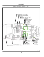
Page 168: ...Water Systems 9 8 FRESH WATER SYSTEM LAYOUT Figure 9 14 ...
Page 169: ...Water Systems 9 9 OPTIONAL AIR CONDITIONING PLUMBING LAYOUT Figure 9 15 ...
Page 170: ...Water Systems 9 10 OPTIONAL GENERATOR PLUMBING LAYOUT Figure 9 16 ...
Page 171: ...Water Systems 9 11 MANUAL TOILET RAW WATER HEAT EXCHANGER LAYOUTS Figure 9 17 ...
Page 172: ...Water Systems 9 12 Notes ...
Page 173: ...Waste Systems Chapter 10 MH37 MARLOW HUNTER LLC V1 R02_110714 ...
Page 174: ...Waste and Sanitation Systems This Page Intentionally Left Blank ...
Page 183: ...Waste and Sanitation Systems 10 9 BILGE SUMP PUMP DRAIN SYSTEM LAYOUT Figure 10 17 ...
Page 184: ...Waste and Sanitation Systems 10 10 AIR CONDITIONING WASTE WATER LAYOUT Figure 10 18 ...
Page 187: ...Waste and Sanitation Systems 10 13 Notes ...
Page 188: ...Waste and Sanitation Systems 10 14 Notes ...
Page 189: ...MH37 Engines Transmissions Chapter 11 MARLOW HUNTER LLC and V1 R02_110714 ...
Page 190: ...Engines and Transmissions This Page Intentionally Left Blank ...
Page 192: ...Engines and Transmissions 11 2 Engines and Transmissions 11 2 Figure 11 2 ...
Page 193: ...Engines and Transmissions 11 3 Figure 11 4 ...
Page 201: ...Engines and Transmissions 11 11 Notes ...
Page 202: ...Engines and Transmissions 11 12 Notes ...
Page 203: ...and MARLOW HUNTER LLC MH37 Sails Rigging Chapter 12 V1 R02_110714 ...
Page 204: ...Sails and Rigging This Page Intentionally Left Blank ...
Page 218: ...Sails and Rigging 12 14 Figure 12 14 GENERAL RIG COMPONENTS ...
Page 219: ...Sails and Rigging 12 15 MAINSAIL JIB SPECIFICATIONS Figure 12 15 ...
Page 220: ...Sails and Rigging 12 16 STANDING RIGGING SPECIFICATIONS STANDARD FURLING RIGS Figure 12 16 ...
Page 222: ...Sails and Rigging 12 18 Figure 12 18 RUNNING RIGGING SPECIFICATIONS ...
Page 224: ...Sails and Rigging 12 20 Figure 12 21 MAINSHEET BOOM OUTHAUL LAYOUT ...
Page 226: ...Sails and Rigging 12 22 VANG LAYOUT CONVENTIONAL SOLID Figure 12 23 ...
Page 228: ...Sails and Rigging 12 24 Figure 12 25 SPINNAKER LAYOUT OPTION ...
Page 229: ...Sails and Rigging 12 25 Figure 12 26 GENERALIZED REEFING LAYOUT ...
Page 230: ...Sails and Rigging 12 26 LAZY JACK LAYOUT WITH OPTIONAL STACK PACK SAIL COVER Figure 12 27 ...
Page 231: ...Sails and Rigging 12 27 STACK PACK SAIL COVER INSTALLATION WITH LAZY JACKS Figure 12 28 ...
Page 232: ...Sails and Rigging 12 28 Notes ...
Page 233: ...MH37 Getting Underway Chapter 13 MARLOW HUNTER LLC V1 R02_110714 ...
Page 234: ...Getting Underway This Page Intentionally Left Blank ...
Page 240: ...Getting Underway 13 6 Notes ...
Page 241: ...MH37 Maintenance Chapter 14 MARLOW HUNTER LLC V1 R02_110714 ...
Page 242: ...Maintenance This Page Intentionally Left Blank ...
Page 257: ...Maintenance 14 15 SLING LOCATIONS Figure 14 3 ...
Page 258: ...Maintenance 14 16 Notes ...
Page 259: ...Glossary Chapter 15 MH37 MARLOW HUNTER LLC V1 R02_110714 ...
Page 260: ...Glossary This Page Intentionally Left Blank ...