background image

2

Introduction

Items Included:

•  (1) ACC-COM-LTE or ACC-P2P-LTE module,  

including internal (pre-installed) SIM card

•  (1) Antenna
•  (1) Tube of RTV sealant
•  (1) Cleaning wipes

Tools/Supplies Required (Not Included):

•  Small Phillips screwdriver with magnetic tip
•  Small flathead screwdriver
•  Additional tools and hardware as required for antenna mounting (radio only)
•  Pedestal mount requires APPBRKT2 (sold separately)

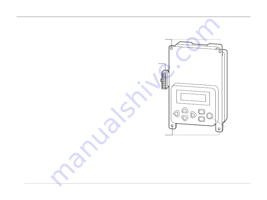
Ribbon cable

Mounting screws

Mounting screws

Enter button

Module Operation

The ACC-COM-LTE provides cellular mobile communications for ACC series 
controllers from a central computer.  
This module may be installed in wall-mounted or pedestal-mounted 
controllers.

Communication Module

Summary of Contents for ACC-COM-LTE

Page 1: ...ACC COM LTE ACC P2P LTE INSTALLATION GUIDE Communications Module and Antenna for LTE Mobile Communications ...

Page 2: ...c tip Small flathead screwdriver Additional tools and hardware as required for antenna mounting radio only Pedestal mount requires APPBRKT2 sold separately Ribbon cable Mounting screws Mounting screws Enter button Module Operation The ACC COM LTE provides cellular mobile communications for ACC series controllers from a central computer This module may be installed in wall mounted or pedestal mount...

Page 3: ...IP data connection for computer control The module contains a data only mobile phone and requires a Hunter account to operate The ACC COM LTE is another version of the module that includes a Site Plan meaning it can link to other controllers on a site with hardwire or UHF radio communications This requires a Hunter Site Plan account ...

Page 4: ...to be mounted on the top of the controller through the provided mounting hole Wall Mount Installation 1 Turn off the AC controller power 2 Remove the facepack door frame Disconnect the facepack door frame ribbon cable open and lift up the door frame to compress the top hinge and tilt out of the lower hinge 3 Locate the communications compartment cover on the back right side of the frame 4 Remove t...

Page 5: ...a rectangular 14 pin connector on one end for the Com module and a DB 15 connector on the other end for connection to the radio The 14 pin connector only plugs one way and is keyed to assist proper orientation Align the connector and push into place on the top of the Com module When the Com module is installed in the opening make sure that the ribbon cable is visible on the back of the unit for co...

Page 6: ... on the antenna bottom to expose the adhesive 5 Route the antenna cables down through the hole into the controller Then press the antenna into place 6 Route the antenna cables through the antenna nut and secure the nut onto the antenna threads Do not overtighten 7 Apply the RTV sealant around the hole filling the gap between the enclosure hole and the mounting threads 8 Route the antenna cables th...

Page 7: ...ing the radio into the radio compartment Install the radio into the radio compartment see radio installation instructions for additional information Connect the AIM BNC to the antenna cable Reapply controller power Verify that the Com module display lights up and displays characters If there is no display 1 Double check ribbon cable connection from Com module to facepack door frame receptacle 2 Do...

Page 8: ...xternal wall beneath it 6 Install the antenna on to the bracket as shown Peel the adhesive covering off the bottom of the antenna feed the cables through the hole in the bracket and press the antenna into place 7 Use the included screws to mount the bracket so that the antenna protrudes into the cutout in the lid 8 Install the cable guides as shown and route antenna wires through them 9 Route the ...

Page 9: ... ready for central communications when the C appears Com Module Controls The Com module controls use the up and down arrow buttons to make selections a and button to change individual settings and an Enter key far right to select and or save settings To Set the Controller Address The controller ID or address is required before any communications can take place An address must be any number between...

Page 10: ...to activate the user account USA 1 800 733 2823 This requires the CID of the LTE module and user account information see attached form To get the CID of the unit Press the up arrow to access the Cell Configure menu and press the enter key Press the up arrow until the Cell CID screen appears You will need this 20 digit number to activate your account with Hunter Hunter Tech Support will confirm the...

Page 11: ...e wireless device and cannot be changed Setup and Addressing of the Com Module Cell Band Normally set to Auto This can also select either LTE G2 or G3 to force selection of a better signal if available Cell Ping This function allows a ping test to the Hunter server The test will make five attempts to contact the IP address Note It is common for the first one or two attempts to fail but the device ...

Page 12: ...sing the left arrow button at any time will show a status display for communications showing transmit and receive activity for each communications type The display shows MOD RAD HW indicating Modem Radio Hardwire and number of data packets sent Under each item MOD RAD and HW the letter T shows transmit activity and R shows receiving data for that communications component The symbol shows other rad...

Page 13: ...tation provides information on configuring sites and the connections for each site Once an ACC COM LTE Site controller is connected via LTE it can share the communications connection with other controllers via radio and hardwire ACC P2P LTE modules do not share connections The following considerations apply to these optional outbound connections UHF Radio The ACC COM LTE module may also be used wi...

Page 14: ...nnect the equipment into an outlet on a circuit different from that of which the receiver is connected Consult the dealer or an experienced radio TV technician for help This device complies with part 15 of FCC rules Operation is subject to the following two conditions 1 This device may not cause harmful interference 2 This device must accept any interference received including interference that ma...

Page 15: ...15 Notes ...

Page 16: ...tries com RC 134 IG 1 20 2020 Hunter Industries Inc Hunter the Hunter logo and all other trademarks are property of Hunter Industries registered in the U S and other countries 1 800 733 2823 Troubleshooting Find more helpful information about your product including installation tips controller programming and more ...

Reviews: