background image

17

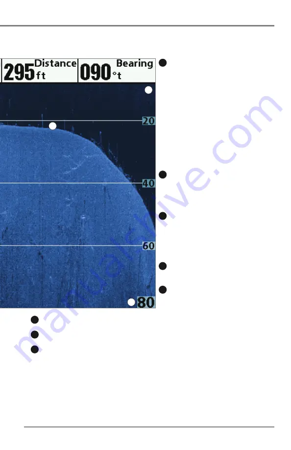
What’s on the Down Imaging Display

Shadows -

result from a lack of reflected sonar

from a particular area and can be as valuable for
interpretation than the sonar reflected by the object
itself. Use shadows to help you see the image in 3
dimensions, oriented in space. You can gain insight
into the actual shape of an object, or the depth to
which it has sunk into the bottom, through shadows
on the display. Objects standing on the bottom cast
a sonar shadow. The longer the shadow, the taller the
object. Fish also cast shadows. You can use the
shadow to interpret how close the fish is to the
bottom.

Topography Changes -

The light part of the

display shows where the beam is hitting hard bottom
or rising terrain. The dark part of the display indicates
soft bottom (sand, mud) or descending terrain.

Bottom Return -

Use the appearance of the

bottom return to determine bottom hardness. Rock
and gravel provide a clearer sonar return than mud
and sand because hard objects reflect sonar better
than soft objects.

Freeze Frame -

Use the 4-WAY Cursor Control key

to move the cursor to an area on the screen.

Clouded Area

may indicate a bait ball and

White

Streaks

may indicate fish.

10

12

13

11

9

NOTE:

Entries in this view that list (with Temp/Speed or GPS receiver) are available if either device is

connected to the HELIX Series Fishfinder. If both devices are connected, then only the information from the
GPS receiver will be displayed on the view.

Upper Range

Lower Range

Structure

8

7

6

(HELIX DI only)

your boat. The razor-thin, high-definition profiling beams produce the detailed sonar data that
interpret the structure and bottom contour, including the following items:

6

7

11

Summary of Contents for HELIX 5 DI

Page 1: ......

Page 2: ...other reproductive harm WARNING Do not travel at high speed with the unit cover installed Remove the unit cover before traveling at speeds above 20 mph NOTE The illustrations in this manual may not l...

Page 3: ...for recycling and recovery of waste EEE Johnson Outdoors Marine Electronics Inc will mark all EEE products in accordance with the WEEE Directive It is our goal to comply in the collection treatment re...

Page 4: ...ange Digital Readouts 21 Combo Views 33 The Menu System 35 Start Up Options Menu 36 X Press Menu 39 Main Menu 40 Quick Tips for the Main Menu 41 Note for all Menu Settings 41 User Mode Normal or Advan...

Page 5: ...authorized international distributors please visit our Web site at humminbird com or contact Humminbird Customer Service at 334 687 6613 NOTE Entries in this Table of Contents which list with Speed I...

Page 6: ......

Page 7: ...our and composition as well as depth directly below the transducer Your HELIX Series Fishfinder sends a sound wave signal and determines distance by measuring the time between the transmission of the...

Page 8: ...lance between depth performance and resolution Low frequencies 83 kHz are typically used to achieve greater depth capability The power output is the amount of energy generated by the sonar transmitter...

Page 9: ...Fishfinder uses Down Imaging technology The Down Imaging transducer scans the water with razor thin high definition beams The beams are wide side to side but very thin front to back The Down Imaging b...

Page 10: ...inition The 20 center beam provides the highest definition while the 60 beam provides wider coverage Depth capability is affected by such factors as bottom hardness and water conditions Whether fishin...

Page 11: ...automatically and your control head can be used on the water You can also select Simulator to learn how to use your control head and save settings in advance for later use See Start Up Options Menu f...

Page 12: ...omizable menus allows you to control what you see on the color display Refer to the following illustration and see Key Functions Views and The Menu System for more information VIEW MENU EXIT screen VI...

Page 13: ...POWER LIGHT key Adjust the Backlight or the Display Background Color Press the POWER LIGHT key to access the Light and Background submenu Use the 4 WAY Cursor Control key to select Light or Background...

Page 14: ...WN or UP Cursor keys to highlight a menu option then press the RIGHT or LEFT Cursor keys to change a menu setting The changes will be activated and saved immediately Freeze Frame In Sonar Views and Do...

Page 15: ...ess the EXIT key to return to the previous level in the menu system From any view press the EXIT key to cycle through the available views in reverse order If Freeze Frame is active press the EXIT key...

Page 16: ...under and adjacent to 7 3 4 5 6 1 2 12 13 Triplog Depth Water depth can be set to alarm when the water becomes too shallow 1 Timer Elapsed time with Speed accessory or GPS receiver Triplog Average Sp...

Page 17: ...bottom hardness Hard bottoms will show a strong second return while soft bottoms will show a very weak one or none at all Cursor Available in Freeze Frame and can be positioned in the Sonar View to pr...

Page 18: ...dow A Real Time Sonar RTS Window appears on the right side of the display in the Sonar Views only The RTS Window always updates at the fastest rate possible for depth conditions and shows only the ret...

Page 19: ...urns are determined by the palette you choose in the Sonar Colors menu option See Sonar Menu Tab to set the Sonar Colors Use Bottom View to select the method used to represent bottom and structure on...

Page 20: ...is changed the Structure ID will display the strongest return as specified by the palette See Sonar Menu Tab Sonar Colors for more information WhiteLine highlights the strongest sonar returns in whit...

Page 21: ...e Active Cursor Press any arrow on the 4 WAY Cursor Control key and the screen will freeze and a cursor will be displayed Use the 4 WAY Cursor Control key to move the cursor over a sonar return and th...

Page 22: ...0 8 Triplog 5 13 Depth Water depth can be set to alarm when the water becomes too shallow 1 Timer Elapsed time with Speed accessory or GPS receiver Triplog Average Speed Average speed reading with Spe...

Page 23: ...lay indicates soft bottom sand mud or descending terrain Bottom Return Use the appearance of the bottom return to determine bottom hardness Rock and gravel provide a clearer sonar return than mud and...

Page 24: ...ide side to side but very thin front to back Use the light and dark parts of the display to interpret the objects under your boat as follows Dark shades represent soft returns mud sand or descending t...

Page 25: ...wn Imaging X Press Menu Down Sensitivity for more information Freeze Frame and Active Cursor Freeze Frame and Active Cursor Press any arrow on the 4 WAY Cursor Control key and the screen will freeze a...

Page 26: ...Rotation Press the VIEW key repeatedly until the view you want to use is displayed on the screen Previous View Press the EXIT key to see the previous view in the View Rotation Press the EXIT key repea...

Page 27: ...the MENU key twice to open the Main Menu Press the RIGHT Cursor key until the Setup tab is selected 2 Press the DOWN Cursor key to highlight Select Readouts and press the RIGHT Cursor key NOTE If the...

Page 28: ...he optional purchase accessories attached see Setup Menu Tab Select Readouts Freeze Frame Use the 4 WAY Cursor Control key to freeze the display and move the cursor over a sonar return The depth of th...

Page 29: ...creen TheFullRangeViewincludes the Zoom Preview Box which shows where the zoomed view is in relation to the full range view The Upper and Lower Depth Range numbers indicate the high and low range of t...

Page 30: ...kHz narrow beam on the left side of the screen and sonar returns from the 200 kHz wide beam on the right side of the screen Digital Readouts shown on the display will change based on the Select Reado...

Page 31: ...l Readouts Depth and Temperature are always displayed The Speed readout is displayed automatically if the appropriate accessory is connected to the Fishfinder The digital readouts in the Big Digits Vi...

Page 32: ...ng X Press Menu Freeze Frame Press any arrow on the 4 WAY Cursor Control key and the Down Imaging View will freeze and a cursor will appear on the screen Use the 4 WAY Cursor Control key to move the c...

Page 33: ...information box 6 zoom magnification box 7 zoomed view 8 lower range 9 Down Imaging View with Active Cursor and Zoom 1 2 3 4 depth 1 water surface temperature 2 voltage 3 triplog 4 speed 5 5 7 8 9 6 2...

Page 34: ...ss the MENU key twice 2 Press the RIGHT Cursor key until the Sonar Menu Tab is selected 3 Press the DOWN Cursor key to select Ice Fishing Mode 4 Press the RIGHT or LEFT Cursor key to select On or Off...

Page 35: ...her X Press Menu Press the MENU key once in the Circular Flasher View Use the X Press Menu to set the Sensitivity Upper Range and Lower Range Depth and temperature are always displayed The Digital Rea...

Page 36: ...once in the Circular Flasher View Use the X Press Menu to set the Sensitivity Upper Range Lower Range and Color Palette Color Palettes The color preview bar in the center of the display indicates the...

Page 37: ...the DOWN Cursor key and the purple cursor line will appear on the display 3 Adjust the Cursor Press the UP or DOWN Cursor keys repeatedly until you reach the chosen depth reading The depth reading of...

Page 38: ...lose the X Press Menu Press the EXIT key 4 Adjust the Zoom Range Press the RIGHT or LEFT Cursor keys repeatedly to adjust the zoom range and select the area you want to magnify The zoomed view is show...

Page 39: ...Side Press the MENU key once and select Active Side from the X Press Menu Choose RIGHT or LEFT to set the active side X Press Menu After you set the Active Side press the MENU key once to access the...

Page 40: ...lling speed the display color palette and the Upper Range and Lower Range see Down Imaging X Press Menu Freeze Frame Press any arrow on the 4 WAY Cursor Control key and the Down Imaging View will free...

Page 41: ...s Normal Simulator and System Status X Press Menu The X Press Menu provides a shortcut to the most frequently used settings and the options on the X Press Menu correspond with the current view Main Me...

Page 42: ...ages Also see Power On for more information Normal Use Normal for on the water operation with a transducer connected If a functioning transducer is connected Normal operation will be selected automati...

Page 43: ...he display in the same way as they would in Normal operation Any menu changes you make will be saved for later use A message will appear often on the display to indicate Simulator mode To exit Simulat...

Page 44: ...off your Fishfinder Self Test displays results from the internal diagnostic self test including unit serial number Printed Circuit Board PCB serial number software revision total hours of operation an...

Page 45: ...or keys to change the menu setting NOTE The X Press Menu will collapse temporarily and the screen will update if it is affected by your menu setting change which allows you to see the effects of your...

Page 46: ...b 3 Press the DOWN or UP Cursor keys to select a specific menu option under that tab 4 Press the RIGHT or LEFT Cursor keys again to change a menu setting A down arrow at the bottom of a menu means tha...

Page 47: ...he menu will open to the same tab as the last time the Main Menu was displayed Note for all Menu Settings The settings in all menus are adjusted in the same way Simply use the 4 WAY Cursor Control key...

Page 48: ...o access the Main Menu 2 Press the RIGHT Cursor key until the Setup tab is selected 3 Press the DOWN Cursor key to highlight User Mode on the Setup main menu 4 Press the LEFT or RIGHT Cursor keys to c...

Page 49: ...Sonar Menu Normal Mode HELIX DI Sonar Menu Advanced Mode HELIX DI 43 Main Menu...

Page 50: ...y of the Sonar Views to access the Sonar X Press Menu NOTE Menu options can be expanded or simplified by setting the User Mode to Advanced or Normal See Main Menu User Mode for details NOTE Menu optio...

Page 51: ...a Combo View is on the screen see Views Combo Views The number setting indicates the percentage taken up by the left side of the Combo View Selecting Left sets the left side of the screen to its small...

Page 52: ...ttom automatically Auto is the default setting Manual You can adjust the Lower Range to lock the unit on a particular depth will be displayed in the lower right corner of the screen to indicate the un...

Page 53: ...me compressed and may be difficult to interpret Regardless of the Chart Speed setting the RTS Window will update at the maximum rate possible for the depth conditions Zoom Level Sonar Zoom View only S...

Page 54: ...ttom return Choose a larger value to see large structure in deeper water NOTE It is possible to set the Bottom Range to be greater than the depth In this case you may see surface clutter in a wavy ban...

Page 55: ...while in any of the Down Imaging Views to access the Down Imaging X Press Menu NOTE Menu options can be expanded or simplified by setting the User Mode to Advanced or Normal See Main Menu User Mode f...

Page 56: ...etting Down Sensitivity Settings 1 to 20 where Low 1 High 20 Default 10 Down Sensitivity controls how the sonar returns are displayed on the Down Imaging Views Increase the Down Sensitivity to reveal...

Page 57: ...bottom sonar returns that might be displayed close together such as those caused by fish suspended close to the bottom or within structure NOTE The cursor must be active for the DI Zoom feature to wo...

Page 58: ...al Models only Default Auto Chart Speed Settings 1 to 9 Ultra where 1 Slow 9 Fast Ultra Fastest Default 5 Chart Speed determines the speed at which the sonar information moves across the display and c...

Page 59: ...her View to access the Flasher X Press Menu NOTE Menu options can be expanded or simplified by setting the User Mode to Advanced or Normal See Main Menu User Mode for details NOTE Menu options are det...

Page 60: ...nar Split Sonar Circular Flasher Big Digits and Down Imaging Sonar Combo Views Upper Range is often used with Lower Range NOTE A minimum distance of 10 feet will be maintained between the Upper and Lo...

Page 61: ...7 DI Auto to 600 feet or Auto to 183 meters International Models only Default Auto Color Palette Circular Flasher View Ice Fishing Mode only Settings Palette 1 Palette 2 Palette 3 Default Palette 3 Co...

Page 62: ...Zoom feature is turned off When the Zoom Level is set to 2x the Circular Flasher View displays a 2x magnified view of the area you choose The zoomed view is shown on the right side of the flasher dial...

Page 63: ...selection NOTE When an alarm is triggered you can silence it by pressing any key The alarm will be silenced and will not be triggered again until a new instance of the alarm condition is detected NOT...

Page 64: ...ll only sound for the battery that is connected to the Fishfinder The Low Battery Alarm should be set to warn you when the battery voltage drops below the safety margin that you have determined Temp A...

Page 65: ...Cursor key Save and Close To save your settings and start the Timer at a later time select Save and Close and press the RIGHT Cursor key Also see Start Timer Digital Readout To display the Timer on s...

Page 66: ...r key until the Sonar tab is selected NOTE Menu options can be expanded or simplified by setting the User Mode to Advanced or Normal See Main Menu User Mode for details NOTE Menu options are determine...

Page 67: ...show the returns from the 200 kHz narrow beam When set to 200 kHz only the returns from the 200 kHz narrow beam will be displayed in the Sonar View the Sonar Zoom View the Big Digits View and the Cir...

Page 68: ...Hz For the best overall image quality and depth select 455 kHz For the sharpest image but limited depth capability select 800 kHz Surface Clutter Settings Low 1 to High 10 Default 5 Surface Clutter ad...

Page 69: ...re displayed above the return that has been classified as being a fish Three different fish size icons represent the intensity of the sonar return and provide an indicator of relative fish size In HEL...

Page 70: ...The RTS Window always updates at the fastest rate possible and only displays returns that are within the transducer beam See What s on the Sonar Display for more information NOTE The Wide RTS Window...

Page 71: ...View which is on the left side of the display See Views Sonar Zoom View for more information 83 kHz Sensitivity Advanced DualBeam PLUS Sonar only HELIX SONAR only Settings 10 to 10 Default 0 83 kHz Se...

Page 72: ...ions the High settings may actually hinder your unit s ability to find the bottom Max Depth Advanced Settings Various see below Max Depth controls the maximum depth of operation When Max Depth is set...

Page 73: ...nsducer is connected to the control head select 2D Element For example if you connect an ice transducer to your Down Imaging unit change the digital depth source to 2D Element in order to display dept...

Page 74: ...for more information Color Bar Settings Off On Default On Color Bar allows you to display or suppress the display of the color bar shown in the full screen Sonar View Ice Fishing Mode Settings Off On...

Page 75: ...olors Down Imaging Views HELIX DI only Settings Blue Amber 1 Amber 2 Brown Green Inverse Gray Green Red Default Amber 1 DI Colors allows you to select which color palette you would like to use for the...

Page 76: ...u then press the RIGHT Cursor key until the Setup tab is selected NOTE Menu options will vary depending on which accessories are attached to the unit NOTE Menu options can be expanded or simplified by...

Page 77: ...ewheel has moved at least once or if the GPS Receiver is connected The available Units Distance settings are determined by your Humminbird model as follows HELIX 5 Meters Kilometers Meters Nautical Mi...

Page 78: ...ee Views to find out how to display Triplog information on the screen Restore Defaults Settings Press the RIGHT Cursor key and follow screen instructions to activate Use this menu choice with caution...

Page 79: ...display in each of the fixed position data windows on the Sonar View screen To leave the data window blank select Off See Views Change Digital Readouts to change the Select Readouts Data windows can...

Page 80: ...fault 0 0 or Off HELIX 7 10 0 to 10 0 feet or 3 0 to 3 0 meters International Models only Default 0 0 or Off Temp Offset Advanced Settings 10 0 to 10 0 degrees Default 0 0 or Off Temp Offset will adju...
Page 81: ...On if you connect the NMEA Output wires of an accessory GPS Receiver cable to another NMEA compatible device such as an autopilot or heading sensor NMEA 0183 is a National Marine Electronics Associati...

Page 82: ...appears on the screen if you don t press any keys during the warning screen at power up Menu settings cannot be saved in Demonstration see Power On and Start Up Options Menu Sound Control Settings No...

Page 83: ...n of water and vinegar WARNING Do not use a chemical glass cleaner on the screen Chemicalsinthesolutionmaycause cracking in the lens of the unit NOTE Do not wipe the screen while dirt or grease is on...

Page 84: ...ing corrosion from the battery terminals or wiring or actually replacing the battery if necessary Fishfinder Defaults to Simulator with a Transducer Attached A connected and functioning transducer wil...

Page 85: ...justed A mix of air and water flowing around the transducer cavitation may be interfering with the interpretation of sonar data See your Installation Guide for suggestions on adjusting the transducer...

Page 86: ...noise re appears To determine whether the boat s engine is the source of the noise increase the RPMs while the boat is in neutral and stationary to see if the noise increases proportionately if noise...

Page 87: ...81 HELIX Control Head Measurements HELIX 5 Control Head Measurements 2 90 in 73 66 mm 3 30 in 83 82 mm VIEW MENU EXIT 7 55 in 191 77 mm 4 28 in 108 71 mm 4 64 in 117 86 mm Gimbal Mount...

Page 88: ...HELIX Control Head Measurements 82 HELIX 5 Control Head Measurements 2 90 in 73 66 mm 2 17 in 55 12 mm VIEW MENU EXIT 7 55 in 191 77 mm 4 28 in 108 71 mm In Dash Mount...

Page 89: ...83 HELIX Control Head Measurements HELIX 7 Control Head Measurements 2 97 in 75 44 mm 3 60 in 91 44 mm 10 54 in 267 72 mm 5 44 in 138 18 mm 5 80 in 147 32 mm Gimbal Mount...

Page 90: ...HELIX Control Head Measurements 84 HELIX 7 Control Head Measurements 2 17 in 55 12 mm 2 97 in 75 44 mm 10 54 in 267 72 mm 5 44 in 138 18 mm In Dash Mount...

Page 91: ...Power Requirement 10 20 VDC LCD 480 V x 800 H Current Draw 650 mA Transducer XNT 9 20 T includes built in temperature probe Transducer Cable Length 20 ft 6 m IPX Rating IPX7 Waterproof Submersible 1m...

Page 92: ...00 kHz 16 10 dB in 455 kHz Target Separation 2 5 inches 63 5 mm Power Requirement 10 20 VDC LCD 480 V x 800 H Current Draw 650 mA Transducer XNT 9 DI T includes built in temperature probe Transducer C...

Page 93: ...Franklin Street Fifth Floor Boston MA 02110 1301 USA To receive a free copy of the Linux software used in this system please send a letter of request with the following information Name First Last Ph...

Page 94: ...E mail service humminbird com Telephone 1 800 633 1468 Direct Shipping Humminbird Service Department 678 Humminbird Lane Eufaula AL 36027 USA Hours of Operation Monday Friday 8 00 a m to 4 30 p m Cen...

Reviews: