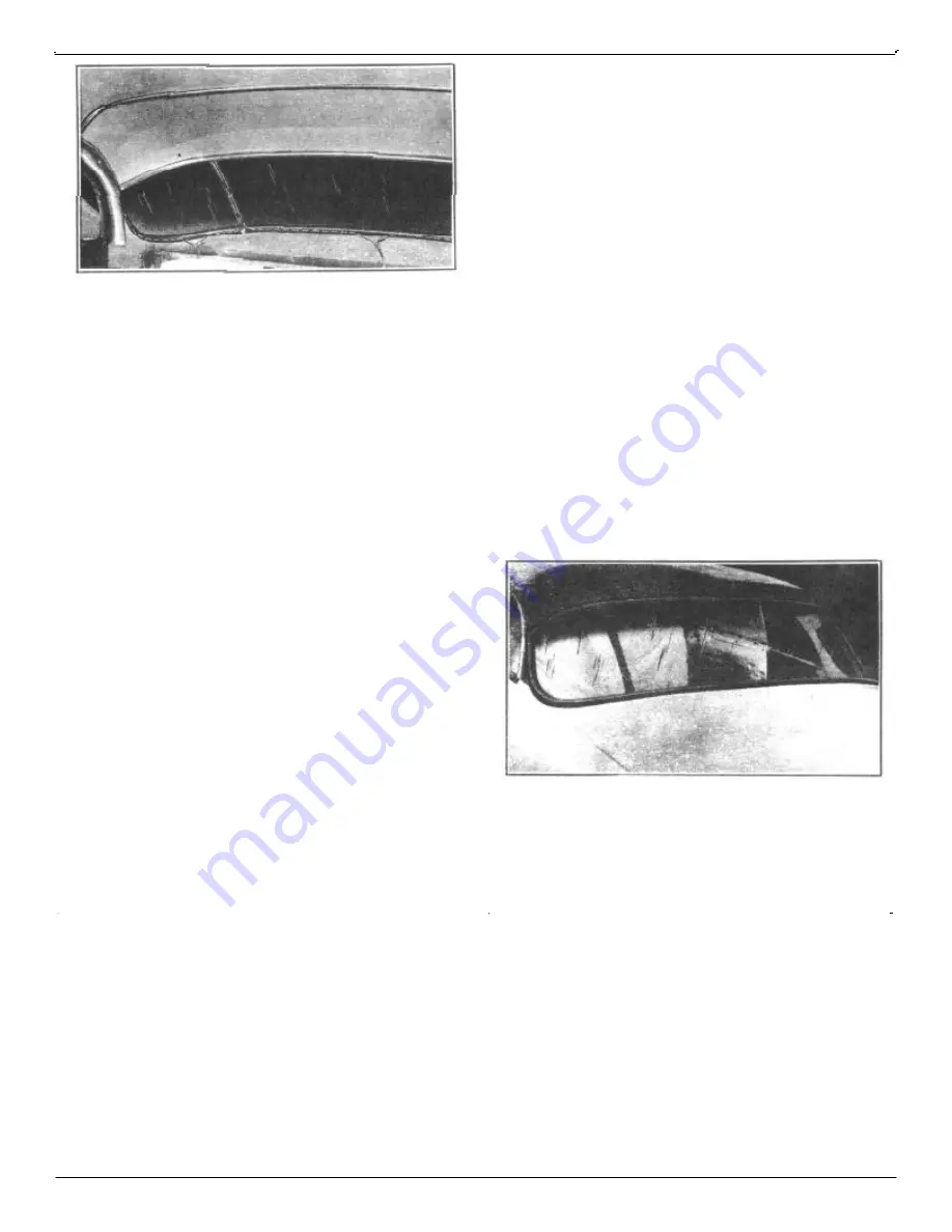
Hudson 1948 Commodore Service Manual Download Page 138

FIGURE 198

 side body rubber lip and lip of recess, Figure 198). Tie 

cords tightly enough to draw the inner edges of the rubber 

channel within the limits of the rear window sections. 

Leave sufficient cord to provide a good hand hold to pull 
the cords, tape loose ends to window glass (to inside).

3. Place a protective cloth over the rear seat back and pack-

age shelf.

4. Apply liquid soap on the inside of the large lip (inner lip) 

of the rubber weatherstrip.

5. With one man inside the car and one man on each side of 

the car (outside of car), position the glass and weatherstrip 
so that inside lip of weatherstrip is over the lip of the 

bottom flange in rear window opening, and that the win-

dow is evenly spaced over the rear window opening.

NOTE: If the glass and weatherstrip is not properly posi-
tioned before the release cords are pulled, it will be neces-
sary to remove the assembly and perform operations 2, 4 
and 5 again.

6. With the two helpers firmly pressing inward and down-

ward  on the glass and weatherstrip assembly and the 

assembly properly positioned in rear window opening, 
pull the center release cord slowly and carefully so that the 

lip of the weatherstrip is raised sufficiently to allow the 

weatherstrip to seat properly in the body recess.

7. After seating the center section, release the cord on the left 

hand section, working the inner lip of the weatherstrip 
over the body flange, using your fingers to pull and posi-

tion the rubber while the helpers steadily push and strike 

the window with the palm of the hand immediately over

 the area being worked. Apply additional liquid soap as 

required to facilitate the installation.

8. After the center and left sections have been properly 

positioned, proceed to the right hand side, proceeding as 
in paragraph 7 above.

NOTE: When performing the above operation the glass 
must be forced into position by blows with a soft rubber 
mallet or with the palm of the hand. Recheck to see that 
the outside lip of rubber  is spaced evenly around rear 
window opening (reposition as necessary).

CAUTION: Do Not Scratch the Glass.

9. Remove the masking tape from window and weatherstrip 

and install the rear window inner and outer vertical 

mouldings.

10. Install Part No. 228715 Sealing Tape 1/8" thick, 1/2" 

wide over groove, between weatherstrip and outside 

body recess completely around  the window in a uniform 
thickness, Figure 199.

11. Install the upper and lower moulding retainers over the sealing 

tape and weatherstrip. Place a small wad of Permagum under 
the moulding retainers at the area of the screw holes. Draw the 

screws down carefully and evenly to spread the sealer uniformly 
and to avoid distorting the moulding retainers.

FIGURE 199

12. Install the roof panel quarter mouldings, (4), Figure 196, the 

upper mouldings outer (3) and lower rear belt mouldings (1).

NOTE: When installing the finish mouldings work from 
the ends to the center to avoid damaging the mouldings.

133    BODY MANUAL    

Summary of Contents for 1948 Commodore

Page 1: ......

Page 2: ...This manual courtesy of Hudson Essex Terraplane Club member Drew Meyer...

Page 3: ...order under the assemblies or units to which they belong Illustrations and pages of this manual are numbered consecu tively The times applying to body operations as shown in the Flat Rate Manual 1 ar...

Page 4: ...gram 1948 1953 Page 95 100 112 113 114 115 119 116 116 119 119 118 115 116 109 110 110 110 95 98 95 98 117 107 101 102 118 119 106 109 124 118 106 119 102 103 104 109 109 98 124 123 117 99 110 122 125...

Page 5: ...ain baffle Page 37 38 67 68 69 70 70 68 68 69 129 129 132 129 136 134 134 134 134 134 135 135 135 135 135 135 131 131 132 133 134 129 130 130 129 47 48 49 49 50 50 51 52 54 52 48 53 53 53 50 53 53 33...

Page 6: ...trim panel by engaging the bottom retainer and aligning clips before driving panel into place FIGURE 1 3 Install pocket trim board 4 Install valance by inserting lower flange between door and pocket t...

Page 7: ...insert a drift or punch through opening in door at E Figure 3 the drift should be so placed below glass channel to hold glass in a raised position when regulator is removed 5 Remove screws C attaching...

Page 8: ...lding 2 Remove small wood block on cars so equipped 3 Remove trim panel see Trim Panel Removal 4 Cut door inner liner as shown in Figures 1 and 2 5 Remove screw A and two screws at B 6 Remove center g...

Page 9: ...door inner panel 4 With the door glass in the down position remove the retainer clips from the regulator arm 5 Remove regulator arm from glass channel and bring the door glass down at the same time t...

Page 10: ...lass Removal FIGURE 8 2 Cut inner liner as shown in Figure 3 to expose screws D and G 3 Remove screw G attaching wing frame to door inner panel 4 Remove screws A and B Figure 8 attaching the wing fram...

Page 11: ...10 and A Figure 11 outward FIGURE 10 FIGURE 11 2 Pull out lock cylinder assembly INSTALLATION 1 From inside of door insert a piece of pointed spring steel wire through the hole C Figure 10 in the doo...

Page 12: ...r door frame anchor plate and remove lock through bottom opening in door INSTALLATION 1 Reverse procedure of removal repair door inner liner 2 Install door trim panel See Trim Panel Installation DOOR...

Page 13: ...ndle end of remote control arm 4 Remove anti rattle spring and pin D from lock end of remote control and withdraw remote control toward hinge hinge side of the door INSTALLATION Reverse procedure of r...

Page 14: ...nd 501 502 503 504 Models The operation of a door lock is effected b y the relation of the door handle shoulder screw to the surface of the trigger lever of the door lock If there is too much clearanc...

Page 15: ...or lock operates normally by depressing the outside handle push button but cannot be released by operating the inside remote control handle after the car has been standing outside in cold weath er it...

Page 16: ...removing the inside trim or door locks DOOR LOCK RELEASE PUSH BUTTON ADJUSTMENT Models IC 1D 2C 2D and 3D The proper operation of the front and rear door push buttons is obtained when the measurement...

Page 17: ...lock rotor and the striker 2 If the door lifts as the dovetail A Figure 23 enters the door striker assembly B the striker is too high and must be lowered 3 The in and out adjustment controls the tight...

Page 18: ...place a jack as near the hinge as possible this will hold the weight of the door as the hinge screws are loosened 2 Use an awl to scribe around the upper and lower hinges before loosening the hinge t...

Page 19: ...t Phillips head screws attaching pillar seal to front pillar 3 Remove all cement and permagum at hinge pockets H 4 Apply a coat of weatherstrip adhesive to the attaching surface of the front pillar we...

Page 20: ...roceed forward until complete weatherstrip has been firmly installed NOTE Do not close door on rubber weatherstrip until rubber cement has sufficient time to set 7 Trim upper end of rear door front ve...

Page 21: ...oulding and pull weatherstrip free from door channel Separate the door lower weatherstrip from the door belt weatherstrip at the point where they are glued together Make a good clean cut at that point...

Page 22: ...STRIP All Models 1948 thru 1953 Except 1C 2C REMOVE AND REPLACE After the door opening weatherstrips and pillar seals have been installed and doors checked for proper closing and alignment check the s...

Page 23: ...LATION 1 Remove all dirt and dried adhesive from door inner panel 2 Apply a thin coat of weatherstrip cement to the door inner panel and the weatherstrip allow cement to be come tacky before installin...

Page 24: ...in the liner at A Figure 33 5 Tuck the bottom ends of liner inside the door panel openings at B Do Not Seal 6 Rub firmly over panel at cemented areas to insure a tight seal NOTE Cement a piece of line...

Page 25: ...at D 9 Apply rubber cement to the scuff plate support seal I and install seal in outside channel of support B 10 Install scuff plate support and seal assembly B on rocker panel extension aligning scre...

Page 26: ...and H Figure 36 4 In stall one center windshield retainer to secure wind shield in proper position NOTE When installing t he windshield retainers do not install the outside retainer next to front hin...

Page 27: ...eter at the pin end ground to a point as shown in Figure 40 and have a length of 9 in order to project under the instrument panel 5 Secure d r a i n tube in place with self tapping screws A Figure 40...

Page 28: ...Clean windshield opening with a putty knife removing all old sealer 2 Remove the reveal moulding joint clip and remove the reveal moulding NOTE The welded flange joint A Figure 41 forming the windshie...

Page 29: ...roster air blocks to be sure they are ce mented securely in place If necessary to install defroster air blocks see Installation of Defroster Air Blocks Page 24 FIGURE 44 12 Install the lower windshiel...

Page 30: ...bracket and mirror WINDSHIELD REVEAL MOULDING Models 1C 1D 2C 2D and 3D REMOVAL 1 Remove windshield wiper arms and blades 2 Remove lower reveal moulding by pushing upward at either corner to release...

Page 31: ...e weatherstrip FIGURE 49 3 Remove the rear view mirror and the self tapping metal screws attaching the garnish mouldings to the windshield opening NOTE To avoid breakage a steady pressure should be ma...

Page 32: ...windshieldgarnishmouldingsandrearviewmirror start all screws before tightening NOTE Care must be taken to install the proper length moulding screws in order to avoid damage to the wind shield glass or...

Page 33: ...to encircle one half of the window Lubricate the cord with paraffin or beeswax 2 Using a tapered fibre or hardwood wedge pry up the outer lip of the rubber weatherstrip Figure 54 and place the cord un...

Page 34: ...f and seat back with a protector cloth 3 Place several thicknesses of masking tape to cover the roof panel area around the rear window to prevent dam age to the body finish when removing the window FI...

Page 35: ...ribbon of weatherstrip sealer to the body recess channel in the weatherstrip Allow only enough sealer to fill the channel recess Use a thin piece of wood approximately 3 4 wide to remove excess sealer...

Page 36: ...ar with Hudson Fabric Cleaner 15 Remove all masking tape and protective coverings and install rear seat cushion 16 Remove all sealer from weatherstrip glass and body finish with mineral spirits REAR W...

Page 37: ...hing may cause the glass to disintegrate The glass should not be hit with any tool if breakage is to be avoided FIGURE 67 3 With the aid of an assistant start at the lower curved section on each side...

Page 38: ...ings Installation FIGURE 70 REAR WINDOW WEATHERSTRIP Models 1C 1D 2C 2D and 3D REMOVAL 1 Remove rear window glass See Rear Window Glass Removal 2 The weatherstrip is held in position over the pinchwel...

Page 39: ...regulator arm roller L from glass and channel as an assembly 6 Remove the regulator handle Concealed pin 7 Remove the arm rest two screws 8 Remove the quarter pocket trim panel 9 Remove the quarter lo...

Page 40: ...Lower the window and apply a coating of cement to window opening to seal glass run channel 4 Insert glass run channel and engage clips in top of window opening 5 Raise window and replace wood block a...

Page 41: ...p opening in quarter panel INSTALLATION Reverse procedure of removal QUARTER WINDOW REGULATOR Models 1C 1D 2C 2D and 3D REMOVAL 1 Remove rear seat cushion and back 2 Remove garnish moulding and regula...

Page 42: ...ommets Do not snap up into the support brackets This prevents undo stretching of the material at this point Work progressively toward the front installing each roof bow into its rubber grommet and sup...

Page 43: ...rror the right and left wind shield garnish mouldings the dome lamp glass and bezel assemblies snap in type 2 Remove the rear seat cushion and rear seat back 3 Remove the rear window glass and weather...

Page 44: ...at this time 4 Stretch headlining down and press into cement around rear window opening To avoid wrinkles and pleats in the material at corners cut several radial slits about 1 1 2 apart and 3 4 deep...

Page 45: ...BODY MANUAL 40 MODELS 1948 1949 FIGURE 78...

Page 46: ...41 BODY MANUAL MODELS 1950 FIGURE 79...

Page 47: ...BODY MANUAL 42 MODELS 1951 FIGURE 80...

Page 48: ...43 BODY MANUAL MODELS 1952 FIGURE 81...

Page 49: ...BODY MANUAL 44 MODELS 1953 EXCEPT 1C AND 2C FIGURE 82...

Page 50: ...45 BODY MANUAL MODELS 1953 1954 1C 1D 2C 2D AND 3D FIGURE 83...

Page 51: ...BODY MANUAL 46 MODELS 1954 4D 5D AND 7D FIGURE 83...

Page 52: ...wiper control assembly INSTALLATION To install reverse procedure of removal INSTRUMENT CLUSTER AND PANEL ASSEMBLY Models 1C 1D 2C 2D and 3D REMOVAL 1 Disconnect the negative battery cable from the bat...

Page 53: ...f ace of the panel See Instrument Cluster and Panel Removal INSTALLATION To install reverse procedure of removal SPEEDOMETER HEAD Models 4D 5D and 7D REMOVAL 1 Remove instrument cluster and panel ass...

Page 54: ...trument panel 3 Remove two screws from base of gauge and disconnect wires and remove gauge INSTALLATION Reverse procedure of removal FUEL GAUGE All Models 1950 1 Remove the two screws attaching the ga...

Page 55: ...d Installation Page 49 CONSTANT VOLTAGE REGULATOR Models 4D 5D and 7D 1 Follow same procedure as for Fuel Gauge Removal and Installation Page 50 FUEL GAUGE CHECK All Models 1948 thru 1950 If the fuel...

Page 56: ...ow fails to operate when connected to car tank unit install a new tank unit CAUTION Do not attempt the repair or calibration of any dash unit or tank unit TEMPERATURE GAUGE CHECK AllModels1948thru1950...

Page 57: ...hat the tank is grounded to the frame TEMPERATURE GAUGE CHECK 1 If the temperature gauge reads up scale with a cold engine and the gas gauge reads up scale with an empty gas tank the constant voltage...

Page 58: ...R SWITCH All Models 1951 thru 1954 Except 1C 1D 2C 2D and 3D REMOVAL 1 Loosen Allen set screw in control knob and remove knob 2 Remove escutcheon nut and pull switch through mounting panel 3 Remove wi...

Page 59: ...ven surface 2 Apply a light coat of trim cement direct to the covering 3 Carefully install the covering to the instrument panel allowing 1 2 of fabric to overlap the instrument panel at finish panel W...

Page 60: ...hield washer attachment REMOVAL 1 Disconnect cables at the wiper motor and lift free of the tension assemblies 2 Remove wiper arms and blades The wiper arms are retained on the burred bushings by a sp...

Page 61: ...uum hose Cable tension can be increased by pushing the tensioners outward advancing the tensioner to the next notch Lubricate the pulleybearingswithlightengineoil ApplyLubri platetothe cables Also che...

Page 62: ...restored by the friction produced in polishing with a dry cloth Under no circumstances use furniture polishes oils or varnishes on leather upholstery Use Ivory soap suds with a sponge wipe off the su...

Page 63: ...ight assembly 7 Front ornament assembly 8 Grille center bar moulding 9 Grille lower moulding 10 Grille lower baffle 11 Grille center moulding 12 Grille center baffle 13 Grille upper moulding 14 Grille...

Page 64: ...ight assembly 7 Front ornament assembly 8 Grille center bar moulding 9 Grille lower moulding 10 Grille lower baffle 11 Grille center moulding 12 Grille center baffle 13 Grille upper moulding 14 Grille...

Page 65: ...bolts attaching grille baffles to center bar 3 Remove two bolts attaching center bar 8 Figure 90 to fender tie panel and to front splash guard 4 Remove center support and splash guard center plate Re...

Page 66: ...3 Except 1C 2C REMOVAL 1 Remove the fender tie panel and hood lock lower support with upper louver and ornament as an assembly 2 Remove screws and bolts attaching the baffle support to the front fende...

Page 67: ...ing the ornament to the ornament support 4 Pull ornament forward and snap out socket and bulb PARKING LIGHT ASSEMBLY All Models 1951 thru 1953 REMOVAL 1 Remove three nuts shakeproof and flat washers a...

Page 68: ...ouver to the parking light ornament assembly 8 Remove the four hexagon head sheet metal screws at taching upper grille louver to center of grille structure and remove the upper grille louver INSTALLAT...

Page 69: ...rews attaching parking light lens INSTALLATION To install reverse procedure of removal RADIATOR MOUNTING U CHANNEL Models 1C 1D 2C 2D and 3D REMOVAL 1 Drain cooling system and remove radiator hoses 2...

Page 70: ...dels 4D 5D and 7D REMOVAL 1 Remove parking light ornament assembly perform oper ations 1 2 3 and 4 under Parking Light Ornament Removal 2 From the opposite side remove the two sheet metal screws attac...

Page 71: ...channel to upper section of grille structure and three sheet metal screws on each side between upper and lower lower grille louvers 5 From under each front fender remove two hexagon head sheet metal...

Page 72: ...m to hood each side NOTE Forward and backward adjustments and up and down adjustments can now be made at the rear of the hood Up or down adjustments at the front of the hood can be made by raising or...

Page 73: ...al and adjust the retainer locking spring by turning the slotted retainer to the right or left as required HOOD LOCK LOWER SUPPORT All Models 1951 thru 1954 Except 1C 1D 2C 2D and 3D REMOVAL 1 Remove...

Page 74: ...fender assembly Loosen the bolts about 1 2 turn Move hinge up or down a small amount each time until desired position is obtained Tighten bolts securely each time before lowering hood 3 The up and dow...

Page 75: ...between hood and cowl panel to support the hood when the hood hinge bolts are removed Figure 105 It is advisable to mark the origi nal position of the hood hinge before removing to facilitate the ins...

Page 76: ...der at cowl panel and at belt moulding with dolphinite sealer No 2465 If necessary to replace the weatherstrip proceed as follows A Apply a coating of rubber cement to the surfaces of the front pillar...

Page 77: ...support chan nel 2 Remove headlamp ring one Phillips head screw 3 Remove the four screws attaching headlamp assem bly and remove headlamp as a unit 4 Remove parking light ornament assembly See Parkin...

Page 78: ...e pillar opening 2 Attach fender to side dust shield and grille structure 3 Reverse procedure of removal on balance of installa tion NOTE Reseal fender at cowl panel and focus headlights FRONT FENDER...

Page 79: ...AL The fender tie panel should be removed with the upper louvers and ornament as an assembly as follows 1 Raise the hood and remove four screws two each side attaching the fender tie panel to the fron...

Page 80: ...Per magum No 576 Sealer starting from base of rear door hinge pillar and crossing quarter panel flange to frame at rear and to area at 2 as shown in Figure 108 Care must be taken to assure that the b...

Page 81: ...lockwise With key in this position press the release pin down with a piece of wire to release the lock cylinder from the compartment door handle and remove the cylinder INSTALLATION To install reverse...

Page 82: ...ock cylinder which is interchangeable on all A Series Models These service locks have a have a long shank to cover all models and must be reworked as illustrated for the different models REAR COMPARTM...

Page 83: ...e striker upward causes the door to close with less pressure and lowering the striker causes the door to close more tightly 3 Tighten both screws securely after making adjustment NOTE The striker is p...

Page 84: ...79 BODY MANUAL MODELS 1948 1949 FIGURE 13...

Page 85: ...BODY MANUAL 80 FIGURE 114...

Page 86: ...81 BODY MANUAL Figure 115...

Page 87: ...STRAIGHTENING All Models 1948 thru 1954 Except 1C 1D 2C 2D and 3D A door header rail that is found to be too 1 ow can be pulled up by gripping it with a clamp and raising with a jack harnessed to pull...

Page 88: ...and body alignment Refer to paragraphs on vertical horizontal and diagonal measurements for full details of checking body door open ings and body squaring up BODY ALIGNING AND TRAMMING All Models 194...

Page 89: ...BODY MANUAL 84 FIGURE 117 FIGURE 118 FIGURE 119...

Page 90: ...forced side ways To square up this section of the body apply the body jack or power tools to the shortest measurements and force the body in that direction a little more than one half the distance bet...

Page 91: ...or forcing tool is in place and after that part of the damaged area has been forced to its proper location T h e torch should be applied to heat those parts that are buckled and wrinkled to a dark red...

Page 92: ...IGURE 121 Inside forward view of skeleton body for all Models 1948 thru 1950 showing interior areas to be sealed FIGURE 122 Inside forward view of skeleton body for all Models 1951 thru 1954 except 1C...

Page 93: ...BODY MANUAL 88 FIGURE 123 Inside forward view of skeleton body 1C 1D 2C 2D and 3D showing areas to be sealed FIGURE 12 Inside rear view of skeleton body 1C 1D 2C 2D and 3D showing areas to be sealed...

Page 94: ...and 3D showing interior and exterior areas to be sealed FIGURE 126 View of cowl panel to frame and pillar All Models except 10 1D 2C 2D and 3D showing areas to be sealed FIGURE 127 View of cowl panel...

Page 95: ...n Figure 128 In addition to sealing the seams at the fender and wheel house and at the frame place a rubberized fibre pad into the front lower corner of the rear fender and frame one each side to insu...

Page 96: ...ed with body sealer on both sides of the joint flange Circle B Figures 131 and 133 indicate the attachment of the wheelhouse and fender to frame side member The sponge rubber between the fender and fr...

Page 97: ...umper guards the hole on the body centerline is covered with a metal plate having a tab on each end These tabs retain the plate in position on the under panel T his plate must also be sealed with body...

Page 98: ...irst determine that the drip moulding is sealed and that the cowl panel to frame at kick panel are properly sealed before sealing the cowl panel to frame and front pillar In Figure 136 the fender has...

Page 99: ...ain trough from the rear pillar to the end of trough Sealer must completely seal opening 3 Re cement loose end of door opening weatherseal and finish by wiping off any excess sealer 4 If it is necessa...

Page 100: ...ASSEMBLY This assembly is a single unit consisting of an electric motor a hydraulic pump and a fluid reservoir Figure 138 shows the hydraulic pump and reservoir in cross section The fluid reservoir is...

Page 101: ...in the car may differ from the position shown in the illustration Operation of the folding top is accomplished with a convenient dash mounted operating knob which operates through an operating valve...

Page 102: ...ated by a single action hydraulic cylinder mechanism The cylinder piston pushes the window upward to a closed position spring tension lowers the window to an open position Individual electrical window...

Page 103: ...fluid raise the car on a hoist and remove cover plate A from the bottom of the well contain ing the Motor and Hydraulic Pump Assembly See Figure 142 Remove the reservoir bail C and the reservoir D and...

Page 104: ...d ing on the position of the control knob on the instrument panel Operation of the valve is controlled by a push pull knob at the left of the steering column At the extreme end of the knob operation i...

Page 105: ...he Id i n place by four attaching screws and is sealed from leakage by a synthetic rubber gasket A second rubber gasket installed between the plastic valve and inner cover seals the valve operating s...

Page 106: ...etic rubber seals form a fluid tight assembly Figure 151 The lower casting forms a yoke which together with a clevis pin provides secure anchorage to the floor bracket The upper casting provides a bea...

Page 107: ...is designed as a unit to provide a mounting for the cylinder assembly 1 and retracting springs 2 and for the cross arms 3 which control the window and hold it in align ment The cross arms are convent...

Page 108: ...rame assembly see Page 103 3 Disconnect hydraulic tube A Figure 154 and solenoid electrical connection B 4 Loosen two 1 2 hex nuts C and remove upper retain ing screw D 5 Remove regulator assembly thr...

Page 109: ...lly lowered The solenoid assembly is provided with a synthetic rubber sealing ring at its upper end above the winding This ring makes a leakproof seal for the lower end of the cylinder The cylinder is...

Page 110: ...ow Then tighten screw G and bolts E 5 Insert and tighten screw H Use a screw driver to align bracket DOOR VENTILATOR WING REGULATOR ASSEMBLY REMOVAL 1 Remove inside door trim and hardware Page 108 2 R...

Page 111: ...el NOTE Manually operated regulator may be removed without removing quarter inner panel With window re moved remove cap screw B and spring panel out until regulator may be lifted out WINDOW OPERATING...

Page 112: ...fective center unit This is necessary since the control knob pivot pin can not be removed from either of the center switches without first removing the end switch REMOVAL 1 Remove the two parallel bus...

Page 113: ...pin retainers Depressing the escutcheon and spring will allow removal of the retainer pins DOOR TRIM PANEL INSTALLATION 1 Cement pocket front and rear corner fillers to the door with trim cement 2 App...

Page 114: ...REAR SEAT CUSHION AND SEAT BACK REMOVAL 1 Rear seat cushion is removed by lifting the forward edge and pulling the seat cushion forward 2 Removal of seat exposes four hex head screws at bottom of seat...

Page 115: ...move window guide channel screws B and C Figure 168 and remove channel by pulling channel down 5 Remove three large Phillips head screws A attaching lock to edge of door 6 Remove remote control anti r...

Page 116: ...alignment gauges with the slotted ends engaging the rear bow and the tapered end with the metal retaining strap on braced against the rear belt line of the body one on each side 19 from center line of...

Page 117: ...screw and necessary tacks to secure curtain and top at belt line 9 Install chrome moulding at rear belt line 10 Install top front header rear chrome moulding narrow and retainer This moulding must be...

Page 118: ...e necessary lateral adjustment and tighten bolts C and D securely FIGURE 175 6 Loosen bolts F and move bracket G up or down in or out until 5 8 clearance is obtained between the top front FIGURE 176 1...

Page 119: ...ils turning the screw out raises the side rails Retighten jam nut on adjusting screw 9 The top side rail front corner bracket J Figures 174 and 177 is preadjusted at the factory with three bolts set m...

Page 120: ...181 5 The door window glass rest channel is also slotted and may be adjusted in the same manner as the regulator assem bly FIGURE 181 VENT WING 1 Remove two screws S Figure 174 attaching the wing cra...

Page 121: ...nflammable any accidental sparks may ignite spilled fluid If the pump motor operates and the battery gravity read ing is at least 1 225 at 70 F unsatisfactory operation may be due to low fluid level i...

Page 122: ...minal marked BAT This terminal is normally hot and the light should light with the switch control knob in any position With the knob in up position the upper or MO terminal should light the test lamp...

Page 123: ...pump Figure 184 The valve A is adjusted to a minimum of 250 pounds and a maximum of 260 pounds per square inch and under no circumstances should it be changed to provide a higher pressure In conjuncti...

Page 124: ...hould now be up to the fluid level line 5 Check all hydraulic connections for leaks BLEEDING HYDRAULIC SYSTEM Bleeding as ordinarily meant by the term is unneces sary with the Hydro Lectric system An...

Page 125: ...BODY MANUAL 120 ALL CONVERTIBLE MODELS 1948 thru 1950 FIGURE 187 ALL CONVERTIBLE MODELS 1951 thru 1953 FIGURE 188...

Page 126: ...121 BODY MANUAL ALL CONVERTIBLE MODELS 1954 FIGURE 189...

Page 127: ...at C 9 Apply rubber cement in the channel and on the lower and back face of the header lower rubber Reassemble lower rubber seal in channel and secure the weatherstrip end by installing screw A 10 In...

Page 128: ...en Tinnerman Nuts L retaining the weatherstrip retainer to header and weatherstrip 3 Remove screws A one each side of header 4 Pull corner seal M loose from lower seal 5 Lower weatherstrip can now be...

Page 129: ...knife Pull weatherstrip from retainer 6 Remove the sheet metal screws I and remove the moulding S INSTALLATION 1 Remove old rubber cement at top header and check Mystik Tape H Figure 190 to be sure i...

Page 130: ...ber filler M Figure 190 is to be replaced apply rubber cement to the top and inside surfaces of the new rubber filler M and install the filler to the outside forward end of the header with front flap...

Page 131: ...atherstrip 8 Carefully trim front end of top side rail front rubber and header rubber so that a smooth closed joint is obtained This is important in correcting water leaks at this point 9 Raise door w...

Page 132: ...eaker H Connection from battery to solenoid defective 3 All units operate slowly A Pump pressure relief valve stuck B Crimped fluid lines C Internal leakage in top operating valve D Improper hydraulic...

Page 133: ...C Broken port plate in top operating valve D Pressure relief valve stuck E Fluid line crimped or plugged F Pump has lost prime A Low battery B Defective motor ground or battery connection C Motor sole...

Page 134: ...rner trim and fillers front and rear are cemented to the door Use care when removing this panel INSTALLATION To install reverse procedure of removal NOTE Install the door trim panel by engaging the pa...

Page 135: ...Insert but do not tighten screws E and G 4 Raise door window and check alignment with the door window Then tighten screws E and G 5 Insert and tighten screw H See Vent Wing Adjust ment before installi...

Page 136: ...by the two screws located at E The two screws E and the two screws located on the inside b e t w e en the inner and outer panel also control the up and down and the front and rearward adjustment NOTE...

Page 137: ...L 1 Remove the rear seat cushion 2 Cover the rear shelf and seat back with a protector cloth 3 Using a wedge shaped fibre tool snap off the rear window exterior lower belt mouldings 1 Figure 196 right...

Page 138: ...e weatherstrip over the body flange using your fingers to pull and posi tion the rubber while the helpers steadily push and strike the window with the palm of the hand immediately over the area being...

Page 139: ...removal procedures DOOR BELT MOULDING The door belt moulding attaching screws are accessible after the door glass and frame assembly and the door vent wing glass and frame assembly have been removed T...

Page 140: ...moulding retainer apply Per magum sealer at the area of the attaching screw holes to form a good seal INSTALLATION To install reverse procedure of removal starting at roof panel quarter moulding and w...

Page 141: ...windshield openings INSTALLATION 1 Apply trim cement at top flange of the rear window opening area between quarter window and rear win dow and at windshield opening Allow cement to be come tacky befo...

Page 142: ...t of the windshield weatherstrip Trim surplus headlining around windshield opening and front pillar post 1 Install the windcord retainer strips at the front pillar post before tightening headlining re...

Page 143: ...REFERENCE Source of Information Date Subject...

Page 144: ...REFERENCE Source of Information Date Subject...

Page 145: ...REFERENCE Source of Information Date Subject...

Page 146: ...REFERENCE Source of Information Date Subject...

Page 147: ......

Reviews: