


U-ONE
®
-SAFETY Compact
Configuration manual SCU C / SRC C / SGS C
USC42_SCU-KonfigManual-en_R5
29
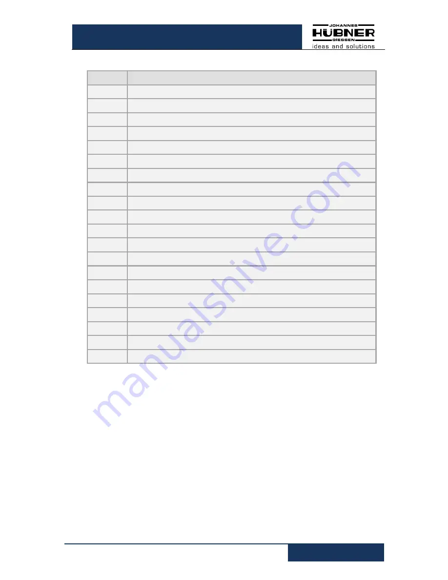
6.5.1 Error table
Error no. Description
30
Undervoltage detected
31, 32
Overvoltage detected
35
Fell below min. temperature
36
Max. temperature exceeded
40
Error reset input
45
Error preset input
48
Error output
50
Fall below system limit
51
System limit exceeded
52
Operating range (system limit) too great
55
Maximum device speed exceeded
60
Start-up during parameterization
61
Start-up during switch test
62
Start-up during preset (software only)
63
Invalid condition for preset
65
Timeout during parameterization
66
Switched off during parameterization
67
Switched off while saving parameters
68
Start-up during factory reset
100-255
Internal diagnostics error detected


