47
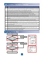
Powering On the BBU
BBU Hardware Installation Checklist
SN
Item
1
All self-made PGND cables are copper-based with the proper wire diameters. No breaking device such as switch
and fuse is allowed for the electric connection of the grounding system. No short circuit is allowed. Each terminal
on the ground bar can be connected with only one wiring terminal of the PGND cable.
2
The redundant part of the power cable or PGND cable is stripped off rather than coiled.
3
The terminals at both ends of the power cable or PGND cable are securely soldered or crimped.
4
The bare wires and the terminal handles at the wiring terminals are coated with heat-shrinkable tubes.
5
The flat washer and the spring washer are well mounted on all OT terminals.
6
All cables are connected securely and reliably. Pay special attention to the cable connections at the bottom of the
cabinet.
7
The cables are neatly and tightly bound. The cable ties are evenly spaced and face the same direction.
8
The power cable, PGND cable, feeder, optical cable and the E1/T1/FE/GE signal cable are bound separately
with a spacing of larger than 3 cm.
9
The cable layout facilitates maintenance and future capacity expansion, and the bending radius of the cables
meet the requirements.
10
All the labels at both ends of the cables are legible.
11
The extra length of each indoor cable tie is cut, and the cut surface is smooth without sharp edges. An extra
length of 3 mm to 5 mm is reserved for each outdoor cable tie.
12
The idle connectors of the cables are properly protected.


