13
Installing the BBU in the APM30H(Ver.A)
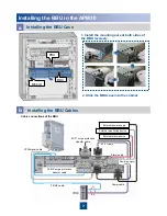
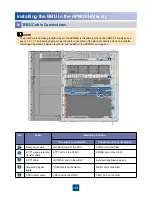
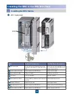
No.
Cable
Installation Position
One end is connected to...
The other end is connected to...
BBU power cable
LOAD3 terminal of the PDU
PWR port on the BBU
E1/T1 surge protection
transfer cable
E1/T1 port on the GTMU
INSIDE port on the UELP
E1/T1 cable
OUTSIDE port on the UELP
External transmission device
Monitoring signal
cable
COM IN port on the HEUA
MON1 port on the BBU
CPRI optical cable
CPRI port on the GTMU
CPRI port on the RRU
a
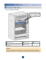
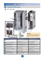
BBU Cable Connections
The procedure for installing the BBU case in the APM30H is the same as that in the APM30. For details, see
p
ages 7 to 12
. The following figure shows the cable connections of the BBU. For details on how to install the
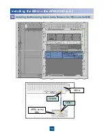
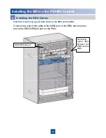
monitoring signal cable between the HEUA and the BBU in the APM30H, see page 14.

