9
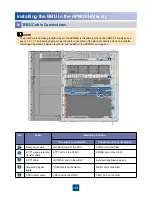
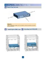
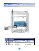
Installing the BBU in the APM30
b
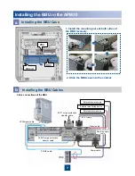
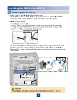
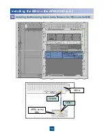
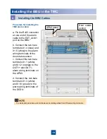
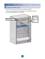
4.3. Strip the jacket off the E1/T1 cable near the grounding point at the lower right
corner of the cabinet to expose the shielding layer
4.4. Thread the E1/T1 cable through the grounding clip. Then, tighten the screw on the
grounding clip to make the shielding layer of the E1/T1 cable in full contact with the
grounding clip. Finally, connect the PGND cable on the grounding clip to the ground bolt
of the APM30.
4.2. Fix the DB26 connector of the E1/T1 cable to the OUTSIDE port on the UELP.
3. Install the E1/T1 surge protection transfer cable.
4. Install the E1/T1 cable.
E1/T1 surge protection
transfer cable
4.1. Cabling the E1/T1 cable.
E1/T1cable
Shielding layer of
the E1/T1 cable
Shielding layer of the E1/T1
cable (25 mm)
Fix the DB25 connector of the E1/T1 surge protection transfer cable to the INSIDE
port on the UELP and the DB26 connector to the E1/T1 port on the GTMU.
Grounding
clip
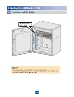
Installing the BBU Cables
Before soldering the connectors to the E1/T1 cable, ensure that both ends of the E1 cable are
disconnected from any devices. In addition, all the connectors should be soldered to the cable.

