38
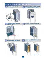
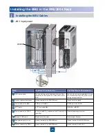
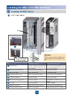
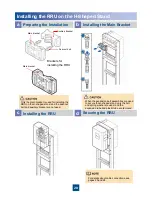
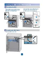
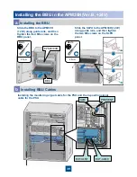
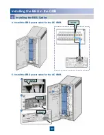
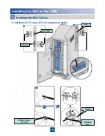
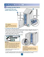
Installing the BBU in the TMC11H(Ver.B)
z
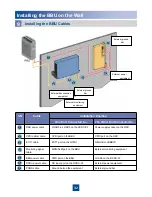
The procedure for installing BBU cables (except the power cable) in the TMC11H cabinet is the same as that
in the APM30H(Ver.B). For details, see the description on pages 33 to 36.
z
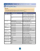
For details on the BBU cable connections, see
BBU Cable Connections
on pages 33.
Installing the BBU Cable
b
Cable
Connector Type
Connects to
CPRI optical cable
DLC
The connectors labeled 2A and 2B are connected to
the optical module on the port labeled CPRI0 to
CPRI5 on the GTMU.
DLC
The connectors labeled 1A and 1B are connected to
the optical module on the port labeled CPRI_W on
the RRU.
E1/T1 cable
DB26 connector
OUTSIDE port on the UELP
The connector needs to
be made on site according
to the field requirements.
Port on the transmission device
E1/T1 surge protection
transfer cable
DB26 connector
E1/T1 port on the GTMU
DB25 connector
INSIDE port on the UELP
FE/GE cable
RJ45 connector
FE0 port at the OUTSIDE side on the UFLP
RJ45 connector
Port on the transmission device
FE/GE surge protection
transfer cable
RJ45 connector
FE0 port at the INSIDE side on the UFLP
RJ45 connector
FE0 port on the GTMU
Monitoring signal cable
between the CMUA and
the BBU
RJ45 connector
MON1 port on the BBU
RJ45 connector
COM_IN port on the CMUA
BBU power cable
3V3 connector
-48V port on the UPEU
OT terminal
LOAD6 port on the DCDU-03B

