background image

Y210 Mobile Phone 
Maintenance Manual 

1 Product Overview 


Issue 1.0 (2012-11-28) 

Huawei Proprietary and Confidential           

Copyright © Huawei Technologies Co., Ltd. 


1.2 Features 

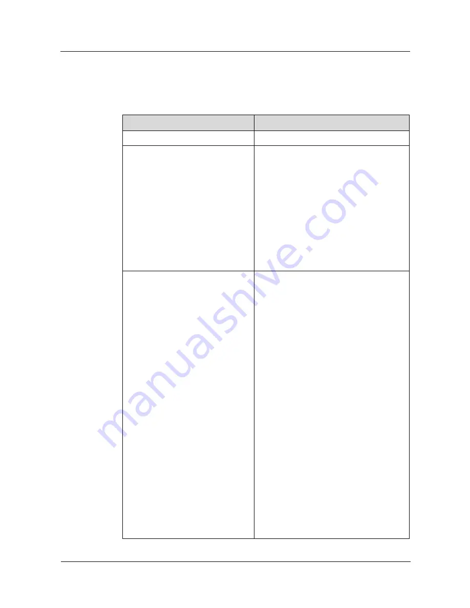
Table 1-1 describes the features of the Y210. 

Table 1-1


Features 

Item 

Description 

Dimensions (H x W x D) 

12.4 mm x 117 mm × 62 mm 

Technical standards 


Y210-0010: W2100/W900, 
GSM900/1800/1900 


Y210-0100: W2100/W900, 
GSM850/900/1800/1900 


Y210-0151: W2100/W1900/W850, 
GSM850/900/1800/1900 


Y210-0200: W2100/W900, 
GSM850/900/1800/1900 


Y210-0251: W2100/W1900/W850, 
GSM850/900/1800/1900 

GSM = Global System for Mobile 
Communications 

Frequency bands 


Y210-0010: W2100/W900, 
GSM900/1800/1900 


Y210-0100: W2100/W900, 
GSM850/900/1800/1900 


Y210-0151: W2100/W1900/W850, 
GSM850/900/1800/1900 


Y210-0200: W2100/W900, 
GSM850/900/1800/1900 


Y210-0251: W2100/W1900/W850, 
GSM850/900/1800/1900 

Frequency ranges: 


WCDMA 900 MHz: 880–915 MHz (uplink), 
925–960 MHz (downlink) 


WCDMA 2100 MHz: 1920–1980 MHz 
(uplink), 2110–2170 MHz (downlink) 


WCDMA 1900 MHz: 1850–1910 MHz 
(uplink), 1930–1990 MHz (downlink) 


WCDMA 850 MHz: 824–849 MHz (uplink), 
869–894 MHz (downlink) 


GSM 850 MHz: 824–849 MHz (uplink), 
869–894 MHz (downlink) 


GSM 900 MHz: 880–915 MHz (uplink), 
925–960 MHz (downlink) 


GSM 1800 MHz: 1710–1785 MHz (uplink), 
1805–1880 MHz (downlink) 


GSM 1900 MHz: 1850–1910 MHz (uplink), 

Summary of Contents for Ascend Y

Page 1: ...Y210 Mobile Phone Maintenance Manual Issue 1 0 Date 2012 11 28 HUAWEI TECHNOLOGIES CO LTD ...

Page 2: ...he customer All or part of the products services and features described in this document may not be within the purchase scope or the usage scope Unless otherwise specified in the contract all statements information and recommendations in this document are provided AS IS without warranties guarantees or representations of any kind either express or implied The information in this document is subjec...

Page 3: ...28 Huawei Proprietary and Confidential Copyright Huawei Technologies Co Ltd ii About This Document Author Prepared by R D Date Reviewed by Maintenance support team Date Approved by Service representative Date Change History Date Version Change Reason Section Description Author ...

Page 4: ...pair Information 4 3 Exploded View 5 4 Components on the PCBA 7 5 Software Upgrade 9 5 1 Upgrade Preparation 9 5 2 Performing an Upgrade 9 6 Maintenance Tools 11 7 Disassembly Procedure 13 8 Assembly Procedure 17 9 Principles and Failure Analysis 21 9 1 Block Diagram 21 9 1 1 Functions of the PCBA 22 9 2 Baseband Unit 26 9 2 1 Power on Management Circuits 26 9 2 2 Charging Management Circuits 30 9...

Page 5: ...ns 46 9 4 6 Tricolor Indicator and Touch Key Backlight Circuits 47 9 4 7 Battery Connector 48 9 4 8 Accelerometer 49 9 4 9 Compass 50 9 4 10 Proximity Sensor 50 9 4 11 Vibration Motor 52 9 4 12 Receiver 53 9 4 13 Microphone 56 9 4 14 Touch Panel 57 9 4 15 SIM Card 58 9 4 16 microSD Card 59 10 Solder Points on the PCBA and BGA Chip 61 11 Functional Tests 67 11 1 MMI Test 67 11 2 Voice Call Test 70 ...

Page 6: ...erview Issue 1 0 2012 11 28 Huawei Proprietary and Confidential Copyright Huawei Technologies Co Ltd 1 1 Product Overview 1 1 Appearance Figure 1 1 shows the appearance of the HUAWEI Ascend Y210 mobile phone Y210 for short Figure 1 1 Y210 mobile phone ...

Page 7: ...0 1900 GSM Global System for Mobile Communications Frequency bands Y210 0010 W2100 W900 GSM900 1800 1900 Y210 0100 W2100 W900 GSM850 900 1800 1900 Y210 0151 W2100 W1900 W850 GSM850 900 1800 1900 Y210 0200 W2100 W900 GSM850 900 1800 1900 Y210 0251 W2100 W1900 W850 GSM850 900 1800 1900 Frequency ranges WCDMA 900 MHz 880 915 MHz uplink 925 960 MHz downlink WCDMA 2100 MHz 1920 1980 MHz uplink 2110 217...

Page 8: ...SIM Charger 5 V 550 mA Battery 1250 mAh Li ion Standby time up to 305 hours Talk time up to 670 minutes depending on network conditions Display Resolution 320 x 480 pixels Liquid crystal display LCD type Thin film transistor TFT Color 262K LCD size 3 5 inches Ports Charging port Micro Universal Serial Bus USB port USB port Micro USB port microSD card slot microSD card slot Headset jack 3 5 mm LRGM...

Page 9: ...exist If you find any errors or have any suggestions please contact Huawei s customer service 2 2 Precautions Only qualified technicians are allowed to perform repair and calibration Perform all operations in electrostatic discharge ESD rooms and wear ESD wrist straps throughout the operations Ensure that all the components screws and insulators are properly installed after repair and calibration ...

Page 10: ...Exploded View Figure 3 1 shows the exploded view of the Y210 Figure 3 1 Exploded view The components listed in the following table are structural parts of the phone and cannot be used as reference to request spare parts Table 3 1 lists the components in the exploded view Table 3 1 Components in the exploded view No Description Quantity 1 Touch panel 1 ...

Page 11: ...cover assembly 1 3 Power button flexible printed circuit FPC assembly 1 4 Receiver 1 5 LCD 1 6 LCD conductive rubber 2 7 Receiver insulation film 1 8 Printed circuit board assembly PCBA 1 9 Volume button FPC assembly 1 10 Motor 1 11 Speaker 1 12 Main antenna support assembly 1 13 Camera support foam 1 14 Camera 1 15 Rear cover assembly 1 16 Battery 1 17 Screws 8 18 Battery cover 1 ...

Page 12: ...s J1302 LCD port Faults caused if damaged LCD malfunctions J1401 SD card slot Faults caused if damaged SD card malfunctions J901 USB port Faults caused if damaged USB connectionfailure U1204 Gravity sensor Faults caused if damaged Gravity sensor malfunctions J1402 SIM card holder Faults caused if damaged SIM card identificationfailure J1403 dual card SIM 2 card holder Faults caused if damaged SIM ...

Page 13: ...logies Co Ltd 8 SP1502 receiver contact J1608 J1608 power button spring Faults caused if damaged Power button malfunctions MIC1501 microphone Faults caused if damaged No sounds for recordings D1602 D1603 D1604 power button LED Faults caused if damaged Functionalkeys backlight off D1601 tri color indicator Faults caused if damaged Indicatoroff ...

Page 14: ... must have more than 1 GB free space Battery The battery level must not be lower than 30 Upgrade file Main upgrade package dload UPDATE app Vendor upgrade package vendor_XXX_XXX UPDATE app Upgrade method Using the microSD card Normal upgrade Forcible upgrade 5 2 Performing an Upgrade To upgrade the Y210 perform the following steps Step 1 Format the microSD card Step 2 Create a dload folder in the ...

Page 15: ...rade the phone using the vendor upgrade package in the same way End If the phone fails to start use either of the following methods to perform a forcible upgrade Install the battery on the phone If the screen splashes remove the battery wait for 5 seconds and re install the battery Press and hold the volume up and down buttons and press the power button The phone then enters forcible upgrade mode ...

Page 16: ... Technologies Co Ltd 11 6 Maintenance Tools Name constant temperature heat gun Usage to heat components Name constant temperature heat gun Usage to heat components Name soldering iron Usage to maintain and solder components Name direct current DC power supply Usage to supply DC current Name soldering table Usage to secure the PCBA ...

Page 17: ...oprietary and Confidential Copyright Huawei Technologies Co Ltd 12 Name lead free solder wire Usage to solder components Name digital multimeter Usage to measure during repair Name toolkit Usage to assemble and disassemble phone Name electric screwdriver Usage to fasten and remove screws ...

Page 18: ...yright Huawei Technologies Co Ltd 13 7 Disassembly Procedure 4 Remove the battery 3 Remove the battery cover Press the upper part of the battery cover and push it towards the bottom 2 Follow the Y210 disassembly instructions 1 Wear an electro static discharge ESD wrist strap and ensure that the strap is grounded properly ...

Page 19: ...gies Co Ltd 14 10 Release the volume key FPC 9 Remove the volume key 8 Use a cover opener to release the latches between the rear cover and the front cover 7 Use the disassembly tab to release the latch in the upper left corner 6 Use the disassembly tab to release the latch in the upper left corner 5 Remove the eight screws from the rear cover ...

Page 20: ...tary and Confidential Copyright Huawei Technologies Co Ltd 15 16 Apply a protective film on the LCD 15 Remove the LCD 14 Release the BTB connector and remove the camera 13 Remove the PCBA 12 Release the two latches on the PCBA 11 Release the BTB connector cable between the touch panel and the LCD ...

Page 21: ...ns single card and dual card versions The pictures for disassembling and assembling a single card Y210 are used The phone disassembly and assembly methods for the two versions are the same 22 The phone is then disassembled 21 Remove the motor 20 Remove the speaker 19 Remove the receiver 18 Remove the power button FPC 17 Apply a protective film on the inner side of the touch panel ...

Page 22: ...1 0 2012 11 28 Huawei Proprietary and Confidential Copyright Huawei Technologies Co Ltd 17 8 Assembly Procedure 4 Install the speaker 3 Install the motor 2 Follow the Y210 assembly instructions 1 Wear an ESD wrist strap and ensure that the strap is grounded properly ...

Page 23: ... to close the latches and secure the PCBA 9 Place the PCBA on the front cover Ensure that the PCBA is in good contact with the front cover at the power button position Snap the latches in place 8 Install the LCD Ensure that the two latches are snapped in place and that the LCD is even 7 Remove the protective film from the LCD 6 Install the power button FPC 5 Install the receiver ...

Page 24: ...nstall the battery Insert it into the battery compartment bottom first 14 Install the eight screws onto the rear cover 13 Install the rear cover Snap the rear cover s bottom and press its top 12 Install the volume button Install the volume button FPC into the ZIF connector and attach them to the front cover 11 Snap the LCD s BTB connector and then the touch panel s BTB connector in place ...

Page 25: ...and Confidential Copyright Huawei Technologies Co Ltd 20 The Y210 has two versions single card and dual card versions The pictures for disassembling and assembling a single card Y210 are used The phone disassembly and assembly methods for the two versions are the same 17 The phone is then assembled ...

Page 26: ... 1 Block Diagram Figure 9 1 shows the block diagram of the Y210 Figure 9 1 Block diagram MSM7X2XA The Y210U uses the MSM7225A is the baseband signal processing chip mainly responsible for processing the input and output of image video audio memory support RF interface and connectivity signals The baseband chip provides keypad LCD microSD card Wi Fi Bluetooth camera microphone and touch panel inter...

Page 27: ...subsystems modules and units as well as their functions Table 9 1 PCBA subsystems modules units and their functions Subsystem Module Unit Function Baseband subsystem MSM7225A Modem subsystem The modem subsystem includes the ARM11 processor modem digital signal processor DSP modem Advanced High performance Bus AHB interruption controller and sleep controller The ARM9 is a 400 MHz modem processor re...

Page 28: ...ty 512 GB RAM random access memory RF subsystem WCDMA and GSM DCS signal transmission and reception AFC circuit APC circuit AGC circuit and each component Performs the RF function of WCDMA signal reception and transmission and mainly includes the RTR6285A RF chip and the peripheral circuit GPS GPS reception Receives and processes GPS signals and mainly includes the RTR6285A chip and the peripheral...

Page 29: ...gineering sample and can be used to debug and test devices during product development USIM card interface Power supply protection circuit USIM card holder Mainly includes the USIM card holder and related connection circuits Keypad and backlight Keypad driver circuit external keypad backlight light emitting diode LED control circuit Supports GPIO for keypad scanning Provides backlight LED When a ke...

Page 30: ...charger Adapter and interface component The charger meets the requirements of China Europe the USA and Australia Charger specifications 90 240 V 45 55 Hz AC input The model differs with different markets The output voltage of the charger is 5 0 25 V The charger must be CE and CCC certified The charger s output current must be able to charge the battery and supply power to the phone for normal oper...

Page 31: ...ignal output channels UVLO Provides the Undervoltage Lockout UVLO function When the input voltage is lower than the threshold for a specific period of time the phone powers off Overheat protection When the on chip junction temperature exceeds 150 C the phone powers off Internal driver circuit Provides one vibration motor driver and one speaker driver Interrupt management The built in interrupt man...

Page 32: ... Mobile Phone Maintenance Manual 9 Principles and Failure Analysis Issue 1 0 2012 11 28 Huawei Proprietary and Confidential Copyright Huawei Technologies Co Ltd 27 Table 9 2 Voltage regulator specifications ...

Page 33: ...he I O connector battery connector is damaged If the I O connector battery connector is not damaged use a DC regulated power supply to supply power to the phone and test the phone s current The power on failure may be caused by any of the following conditions No current Figure 9 2 No current Replace J902 N Power on failure no current Is the battery connector J902 normal Replace Q201 N Is Q201 norm...

Page 34: ...problem solved Is U210 s output voltage normal Replace U201 N N Replace U401 N Does X301 have 32 768 kHz output Replace U601 and reinstall the phone s firmware Is the problem solved Y Replace X301 N End Y Y Excessive current Excessive current is caused by short circuits When excessive current occurs to prevent damage to components do not connect the charger to the phone Power on failure due to exc...

Page 35: ...Excessive current Check whether VPH_PWR and PM outputs are short circuited N Power on failure excessive current Test the VBAT circuit Is it a short circuit Is J902 normal Re solder or replace J902 N Y Replace U401 N Is Q201 normal Remove U201 Do short circuits still exist Y Replace Q201 N Replace U201 Y Y 9 2 2 Charging Management Circuits Figure 9 5 Charging management circuits ...

Page 36: ...s J901 poorly soldered Re solder J901 Is the battery in good contact with the battery connector End Does VPH_PWR have voltages Repair or replace J902 Replace U201 N Y Y Y N N Is the battery damaged Replace the battery Y N Y Y Is there voltage difference between Q201 pin 2 and pin 3 Replace Q201 N Is the charger working properly Replace the charger N Y 9 3 RF Unit 9 3 1 RF Failure Troubleshooting T...

Page 37: ...en the RF cable is not inserted are J3204 s pin 1 and pin 2 connected Check J3204 Are U3201 s control signals normal Check U401 Are U3501 s GSM output and DCS output approximately 33 dBm and 30 dBm respectively Check U3201 and U401 Check U3501 Y N Y Y Y N N Do U3801 s pin A10 and pin A9 have output Check U3801 N Y Table 9 3 and Table 9 4 describe the working status of the GSM DCS power amplifier U...

Page 38: ... 11 28 Huawei Proprietary and Confidential Copyright Huawei Technologies Co Ltd 33 H voltage higher than 1 3 V L voltage lower than 0 5 V WCDMA transmission failure use W2100 as an example Before starting the following process ensure that the USIM card and the antenna are well connected ...

Page 39: ...the RF cable is not inserted are J3204 s pin 1 and pin 2 connected Check J3204 Are U3201 s control signals normal Check U401 Is the insertion loss between U3304 s pin 1 and pin 3 approximately 1 1 1 4 dB Check U3201 and U401 Check U3304 Y N Y Y Y N N Is U3301 s output24 dB Check U3301 N Y Y Y Is the insertion loss between U3302 s pin 2 and pin 9 approximately 0 6 dB Check U3302 N Check U3801 N Doe...

Page 40: ...ifier working status 1 PA_R PA_R1 Mode L L HI Power L H MI Power H H LO Power H 1 3 1 8 V L 0 5 V 9 3 2 GPS The GPS channel consists of filter U4102 filter U4103 and LNA U4101 GPS signals are sent to the RTR6285A s input interface after going through the filters and LNA Figure 9 9 shows the circuit Figure 9 9 GPS circuit 9 3 3 Wi Fi Bluetooth FM Module The Y210 uses a WCN2243 Bluetooth FM 2 in 1 m...

Page 41: ...UX_PCM_DIN PCM input GPIO_68 AUX_PCM_DOUT PCM output GPIO_70 AUX_PCM_SYNC PCM synchronization GPIO_71 AUX_PCM_CLK PCM clock GPIO_107 MSM_WAKES_BT Waking up the host GPIO_83 BT_WAKES_MSM Waking up the Bluetooth The MSM7225A provides SDIO3 interfaces that are directly connected to the Wi Fi module s SDIO signal output Table 9 8 describes the signals definitions Table 9 8 Signal definitions SDIO3 int...

Page 42: ...ry Processor Interfaces MIPIs to send instructions and data to the LCD The Y210 s LCD uses MIPIs supporting a 60 Hz refresh rate and requiring only one pair of differential clock lines one pair of differential signal lines and one pair of power supply lines The LCD also supports frame synchronization using the MDP_VSYNC signals GPIO_097 as data transmission synchronization signals to avoid screen ...

Page 43: ...DSI_LANE1_N Synchronization signal Frame synchronization clock MDP_VSYNC_ P GPIO97 Clock signal MIPI clock MIPI_DSI_CLK _P MIPI_DSI_CLK_P MIPI clock MIPI_DSI_CLK _N MIPI_DSI_CLK_N Control signal Reset LCD_RESET_N GPIO129 Identification signal LCD model identification LCD_ID0 GPIO9 PM8029 LCD model identification LCD_ID1 GPIO10 PM8029 Y210 s LCD backlight control The Y210 uses a 3 5 inch LCD whose ...

Page 44: ...uawei Technologies Co Ltd 39 Figure 9 11 LCD backlight circuit Backlight signals Anode of the backlight LED LED_A Anode of the backlight LED Cathode of the backlight LED LED_K Cathode of the backlight LED Brightness control signals from the LCD PWM_OU T Reserved Brightness control signals from the phone s main chip LCD_BL_ PWM GPIO1 PM8029 ...

Page 45: ... Return the phone to the factory Clean the LCD 50 pin male female connectors Snap them in place again Is the problem solved End Y N Re install the phone s firmware Is the problem solved End Y N Replace the LCD Is the problem solved End Y N 9 4 2 Camera The Y210 uses a 3 0 megapixel full frame camera The 3 0 megapixel full frame camera uses a 24 pin board to board BTB connector and is controlled by...

Page 46: ... Power supply to the camera autofocus motor CAM_AVDD VREG_L17 PM8029 AVDD 2 85 CAMIF_MCLK GPIO_015 MSM7225A MCLK 1 8 Camera reference clock MCAMIF_SHDN GPIO_119 MSM7225A PWDN 1 8 Camera shutdown signal CAM_VCM_PD_N GPIO_07 MSM7225A 1 8 Camera autofocus motor control signal I2C0_SCL GPIO_060 MSM7225A I2C_SCL 1 8 I2C control signal I2C0_SDA GPIO_061 MSM7225A I2C_SDA 1 8 MCAMIF_RESET GPIO_049 MSM7225...

Page 47: ... signal MIPI_CSI2_LANE0_N MIPI_CSI2_LANE0_N MIPI DATA Data communication signal The camera interface circuit is designed for compatibility with multiple types of cameras The Y210 uses a 3 0 megapixel full frame camera so the CAM_VCM_PD_N and VREG_CAM_2P85 lines are not used Troubleshooting Camera Failure Figure 9 14 Camera failure Failure to take photos or record video using the camera Replace the...

Page 48: ...td 43 9 4 3 USB Figure 9 15 USB circuit Troubleshooting USB Connection Failure Figure 9 16 USB connection failure USB connection failure Re install the phone s firmware Is the problem solved End Is the 5 pin mini USB connector poorly soldered Return the phone to the factory Re solder the USB connector Y N Y Use a normal USB cable Is the problem solved End Y N N ...

Page 49: ...oltage is at a high level After a headset is inserted pin 3 and pin 4 are closed and the headset detection voltage is at a low level indicating the insertion of a headset The HS_DETECT GPIO86 pin is used to detect the headset insertion The HSED_MICBIAS PM8029 HSED_BIAS1 supplies power to the headset microphone The HSED_HSKEY_ADC PM8029 MPP5 is used to detect the headset button press The Y210 suppo...

Page 50: ...n Replace the headset jack Replace the headset Is the problem solved Return the phone to the factory End Y Y N Is the in call volume set to a normal level End N N Y The headset button cannot be used to answer a call Figure 9 19 Headset button malfunctioning The headset button cannot be used to answer a call Insert the headset Is the voltage on J1101 s pin 4 at a low level Return the phone to the f...

Page 51: ...eys and buttons three of which are the Menu Home and Back keys on the touch panel The MSM7225A s GPIO_42 and GPIO_41 pins are connected to the volume up and down buttons The side key FPC is connected to the PCBA via the ZIF connector J1605 The power button press is detected by the PM8029 s KYPD_PWR_N pin The power button FPC is connected to the PCBA using press fit contacts Figure 9 20 Key and but...

Page 52: ...on the FPC in good contact with the dome sheet Clean the keypad and the dome sheet N Y 9 4 6 Tricolor Indicator and Touch Key Backlight Circuits The Y210 s battery charging indicator tricolor indicator provides red green and blue light sources that are driven by the PM8029 s three LED driver Table 9 12 Light source and driver pins Light Source Driver Pin PM8029 Remarks Red LED_RED_DRV_N MPP3 Adjus...

Page 53: ...supply power to the backlight LEDs The keypad backlight is provided by two white LEDs The light from the LEDs is transmitted to the key area using a light guide film Table 9 13 Keypad backlight driver Keypad Backlight Driver VPH_PWR Power supply Backlight power supply KPD_DRV_N Backlight driver pin When this pin s voltage is at a low level the two backlight LEDs turn on Figure 9 23 Touch key backl...

Page 54: ...right Huawei Technologies Co Ltd 49 9 4 8 Accelerometer Figure 9 25 Accelerometer circuit Table 9 14 Accelerometer pins Component Pin Network MSM7225A Pin Description SCL I2C1_SCL GPIO_131 I2C bus SDA I2C1_SDA GPIO_132 INT1 MEMS_INT1 GPIO_28 Accelerometer interrupt signal INT2 MEMS_INT2 GPIO_111 Accelerometer interrupt signal sleep ...

Page 55: ...right Huawei Technologies Co Ltd 50 9 4 9 Compass Figure 9 26 Compass circuit Table 9 15 Compass pins Component Pin Network MSM7225A Pin Description SCL I2C1_SCL GPIO_131 I2C bus SDA I2C1_SDA GPIO_132 DRDY COMPASS_INT GPIO_18 Compass interrupt signal 9 4 10 Proximity Sensor The Y210 uses a 3 in 1 light proximity and infrared sensor ...

Page 56: ...tial Copyright Huawei Technologies Co Ltd 51 Figure 9 27 Sensor circuit Table 9 16 Sensor pins Component Pin Network MSM7225A 0 Pin Description SCL I2C1_SCL GPIO_131 I2C bus SDA I2C1_SDA GPIO_132 INT PRO_INT GPIO_17 3 in 1 interrupt signal Functions Detect the intensity of environmental light Detect the proximity of objects ...

Page 57: ...ng a call The phone is in portrait orientation no headset is connected handsfree mode is disabled Is U1207 poorly soldered or dirty Re solder clean or replace U1207 Re install the phone s firmware Is the problem solved Return the phone to the factory End Y N Y Is the touch panel s light sensor hole dirty or blocked Clean the hole Y N N 9 4 11 Vibration Motor Figure 9 29 Vibration motor circuit The...

Page 58: ...eshooting Vibration Failure Figure 9 30 Vibration failure Vibration failure Is the voltage on VIB_DRV_N equal to the battery voltage Replace D902 Replace the motor Is the problem solved Return the phone to the factory End Y N Y Re install the phone s firmware Is the problem solved End Y N N 9 4 12 Receiver The receiver receives differential earphone output from the MSM chip ...

Page 59: ...Analysis Issue 1 0 2012 11 28 Huawei Proprietary and Confidential Copyright Huawei Technologies Co Ltd 54 Figure 9 31 Receiver circuit The MSM chip s EARI output signal is connected to the receiver D1503 and D1504 are the ESD protection components on the receiver ...

Page 60: ...55 Troubleshooting the Failure that No Sound Can Be Heard During a Call Figure 9 32 No sound during a call No sound is heard during a call Replace the receiver Is the problem solved End Does the phone mistakenly detect the insertion of a headset Return the phone to the factory Replace the headset connector Y N Y Is the in call volume set to a normal level End N N Y ...

Page 61: ...bile Phone Maintenance Manual 9 Principles and Failure Analysis Issue 1 0 2012 11 28 Huawei Proprietary and Confidential Copyright Huawei Technologies Co Ltd 56 9 4 13 Microphone Figure 9 33 Microphone circuit ...

Page 62: ... during a call No sound can be heard by the other party during a call Replace the microphone Is the problem solved End Is the MIC_BIAS voltage equal to 1 8 V Return the phone to the factory Check U201 N N Y Re install the phone s firmware Is the problem solved End Y Y N 9 4 14 Touch Panel Figure 9 35 Touch panel circuit The Y210 s 3 5 inch capacitive touch panel has a touch key area containing thr...

Page 63: ...Touch panel s I2C data TOUCH_RST_N GPIO_96 MSM7225A Touch panel reset signal 9 4 15 SIM Card The MSM7225A is not compatible with the SIM card interface The PM8029 s MPP pins are used to convert voltage levels of the signals for communication between the MSM7225A and the SIM card The voltage of VREG_L16_UIM1 can be set to 1 5 3 05 V The USIM interface s operating voltage is usually 1 8 V or 3 0 V T...

Page 64: ...19 USIM card circuit 9 4 16 microSD Card The microSD card connector s SD_DETECT pin is used to detect the insertion of a microSD card When a microSD card is inserted the pin is grounded and its voltage is at a low level When no microSD is inserted its voltage is at a high level The U1402 is an electromagnetic interference EMI and ESD protection component for the microSD card ...

Page 65: ...Y210 Mobile Phone Maintenance Manual 9 Principles and Failure Analysis Issue 1 0 2012 11 28 Huawei Proprietary and Confidential Copyright Huawei Technologies Co Ltd 60 Figure 9 36 microSD card circuit ...

Page 66: ... and Confidential Copyright Huawei Technologies Co Ltd 61 10 Solder Points on the PCBA and BGA Chip Red R 255 G 0 B 0 Vacant point Green R 0 G 255 B 0 Ground point Blue R 0 G 0 B 255 Solder point Figure 10 1 Figure 10 2 Figure 10 3 and Figure 10 4 show magnified views of sections Figure 10 5 shows the complete PCB view ...

Page 67: ...Y210 Mobile Phone Maintenance Manual 10 Solder Points on the PCBA and BGA Chip Issue 1 0 2012 11 28 Huawei Proprietary and Confidential Copyright Huawei Technologies Co Ltd 62 Figure 10 1 PM section ...

Page 68: ...obile Phone Maintenance Manual 10 Solder Points on the PCBA and BGA Chip Issue 1 0 2012 11 28 Huawei Proprietary and Confidential Copyright Huawei Technologies Co Ltd 63 Figure 10 2 MSM7225A NAND MCP section ...

Page 69: ...ntenance Manual 10 Solder Points on the PCBA and BGA Chip Issue 1 0 2012 11 28 Huawei Proprietary and Confidential Copyright Huawei Technologies Co Ltd 64 Figure 10 3 Wi Fi Bluetooth FM section Figure 10 4 RTR8285A section ...

Page 70: ...10 Mobile Phone Maintenance Manual 10 Solder Points on the PCBA and BGA Chip Issue 1 0 2012 11 28 Huawei Proprietary and Confidential Copyright Huawei Technologies Co Ltd 65 Figure 10 5 Complete PCB view ...

Page 71: ...Y210 Mobile Phone Maintenance Manual 10 Solder Points on the PCBA and BGA Chip Issue 1 0 2012 11 28 Huawei Proprietary and Confidential Copyright Huawei Technologies Co Ltd 66 ...

Page 72: ...icroSD card functions If a microSD card is found and is available the test passes otherwise the test fails If this test passes the next test automatically starts 2 SIM card test SIM card test Automatically test whether the SIM card can be recognized If the SIM card cannot be recognized a message will be displayed indicating that this test fails If this test passes the next test automatically start...

Page 73: ... edges The areas near the route that your finger passes should turn red Press the volume down button to start the next test 10 Proximity test Proximity and light sensor s proximity detection function Place the light shielding plate approximately 4 mm above the light hole If the portrait icon changes to an in call icon the function is normal If this test passes the next test automatically starts 11...

Page 74: ...sting a headset to be inserted will be displayed After a headset is inserted the phone will search for and play an FM channel Three frequencies 88 MHz 98 MHz and 107 MHz will be tested The 88 MHZ frequency will be tested first To test the next frequency touch Next Remove the headset Press the volume down button to start the next test 19 Headset button test Headset button test Insert the headset Th...

Page 75: ...g test results Display the MMI test results Failed test items will be listed 11 2 Voice Call Test To test the voice call function perform the following steps Step 1 Install a UIM card and battery on the phone Step 2 Press the power button to power the phone on Step 3 Check whether the signal strength displayed on the LCD is normal given that the network is normal Step 4 Make a call to a fixed line...

Reviews: