background image

INSTALLATION 

&


USER’S GUIDE

®

4530EX

®

FOR SALES, PRODUCT 

INFORMATION & 

TECHNICAL SUPPORT

Uplink Security, LLC. 

3330 Cumberland Blvd.  

Suite 700 

Atlanta, GA 30339

1-(888) 9-UPLINK, 1-(888)-987-5465

Fax 1-(888)-542-9105

[email protected]

www.uplink.com

4G PRIMARY CELLULAR 

ALARM COMMUNICATOR

Summary of Contents for 4530EX

Page 1: ...FOR SALES PRODUCT INFORMATION TECHNICAL SUPPORT Uplink Security LLC 3330 Cumberland Blvd Suite 700 Atlanta GA 30339 1 888 9 UPLINK 1 888 987 5465 Fax 1 888 542 9105 sales uplink com www uplink com 4G PRIMARY CELLULAR ALARM COMMUNICATOR ...

Page 2: ...l other trademarks are the property of their respective owners PRODUCT ID 202132UP453E01 4G PRIMARY CELLULAR ALARM COMMUNICATOR TABLE OF CONTENTS Table of Contents 2 Introduction 4 Key Features 5 6 Warranty Limitation of Liability 7 8 FCC and Regulatory Compliance Part 15 9 FCC RF Exposure Information 10 Technical Support 11 Installation 12 23 A General Considerations 12 B DIP Switch Settings 12 C...

Page 3: ...s the phone line connection The Uplink 4530EX unit will intercept the alarm panel s digital dialer output when the panel has an event to report and communicate with the panel as if it were a central station alarm receiver Once the 4530EX completes a communications session with the alarm panel it will transmit the alarm information using the local GSM cellular communications network The Model 4530E...

Page 4: ...nts KEY FEATURES A FULL DATA Reporting Compatible with most alarm panels using Contact ID SIA DC 05 Standard SIA FSK Level 1 SIA DC 03 Standard Modem IIe IIIa IIIa2 or Pulse 4 2 digital dialer formats All information sent by the alarm panel in these formats account number zone information User IDs etc will be sent to the central station using the GSM network B Power Requirements Requires constant ...

Page 5: ... Uplink expressly disclaims any warranty express or implied extending to such end user consumer or parties including without limitations any implied warranties or merchantability and fitness for a particular purpose End user consumers with questions concerning an Uplink product are directed to contact the alarm security system dealer or installer from whom they purchased the product Distributors d...

Page 6: ...th Part 15 of the FCC Rules Operation is subject to the following two conditions 1 this device may not cause harmful interference and 2 this device must accept any interference received including interference that may cause undesired operation This equipment has been tested and found to comply with the limits for a Class B digital device pursuant to Part 15 of the FCC Rules These limits are design...

Page 7: ...he best transmitted and received signal strength for the cellular radio If the installer does not have a very strong cellular signal in his area he may want to first power the unit from a portable 12V DC source switch on S4 and move the unit to a location that gives him the best signal strength b Proximity to the alarm panel and where to route the 4530EX s relay output that connects to an alarm pa...

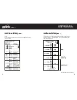
Page 8: ... S4 to ON the five LEDs indicate the follow signal strength information GOOD UNACCEPTABLE MINIMUM ACCEPTABLE INSTALLATION continued next page RECEIVED SIGNAL STRENGTH OFF FLASH ON LED1 LED2 LED3 LED4 LED5 GREEN 70dBm GREEN LED1 LED2 LED3 LED4 LED5 GREEN 60dBm GREEN GREEN LED1 LED2 LED3 LED4 LED5 GREEN 90dBm LED1 LED2 LED3 LED4 LED5 GREEN 100dBm LED1 LED2 LED3 LED4 LED5 RED 110dBm No Signal All LED...

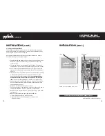
Page 9: ...sition The LEDs are now operating in RSSI Mode Locate a good mounting position based on a good Received Signal Strength Indication RSSI It is recommended that the installation location demonstrate an RSSI of at least 80 dBm two solid green LEDs The minimum acceptable RSSI is 90 dBm 1 solid green LED 5 Position the bottom of the 4530EX enclosure where it will be installed Use four 4 6 screws and mo...

Page 10: ...te for this Output is as follows OUTPUT DEFAULT STATE DEFAULT DEFINITION 1 Configurable normally closed Loss of cellular service See Figure 2 as an example of how to connect the 4530EX to the alarm panel IMPORTANT Make all of the connections to the 4530EX in the powered down state Once all of the connections have been established turn power on INSTALLATION continued next page ALARM PANEL Host Pane...

Page 11: ...sed bell circuits may require a 1K Ohm resistor in the circuit Contact Technical Support for further details 3 Sampled Siren This mode configures the unit to be tripped from a siren driver or a panel with a built in siren driver The unit reads a steady tone as a fire signal and a yelping tone as a burglary signal NOTE The input assumes that a speaker is connected to the panel If you are not using ...

Page 12: ...ort that condition and its Restoral to the monitoring Central Station INSTALLATION cont G Activating the 4530EX The 4530EX is programmed OTA Over the Air by accessing the Uplink Dealer website or by calling Uplink Customer Service at 1 888 9UPLINK 1 888 987 5465 New Dealer Enrollment For new dealers customers you must first establish an account with Uplink by visiting the Uplink website www uplink...

Page 13: ...aler output and reported the event to the central monitoring station c If using the Output Relay on the 4530EX go back to the dealer website and use the Switch Output Relay command to test the relay Make sure the premises alarm panel properly detects the relay s change of state and that it reports the proper event to the monitoring central station d Finally remove DC Power from the 4530EX and trip...

Page 14: ...ce 600 ohms Ringer Equivalence 0 3 REN Mode Loop start 26 mA typical POWER REQUIREMENTS Input Voltage 12V DC Normal Current On Hook 125 mA Maximum Current Off Hook 600 mA Radio during Transmission Average Current Peak Current 215 250 mA 1 3 1 5 A UL Power Requirements Uninterruptable Class 2 power supply 12V DC 1 2 A SPECIFICATIONS cont RADIO Frequencies 850 1900 MHz Sensitivity 106 dB typical ENV...

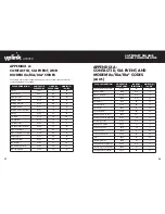
Page 15: ...toral R158 KR 12 Holdup Alarm E122 HA 10 Holdup Restoral R122 HR 12 Low Battery E302 YT 4B Low Battery Restoral R302 YR 4C Low Temperature E159 ZA 10 APPENDIX A CONTACT ID SIA EVENT AND MODEM IIe IIIa IIIa2 CODES cont EVENT DESCRIPTION CONTACT ID EVENT CODE SIA DC 03 EVENT CODE MODEM IIe IIIa llla2 Low Temperature Restoral R159 ZR 12 Medical Alarm E100 MA 10 Medical Restoral R100 MR 12 Opening E40...

Page 16: ...e E302 YT 4B 240 Low DC Restoral R302 YR 4C 240 Cable Supervision Trouble E616 YX 11 242 Cable Supervision Restoral R616 YZ 12 242 Cellular Service Loss E355 YC 11 243 Cellular Service Restoral R355 YK 12 243 4530EX UNIT DISABLED E616 YX 11 245 4530EX UNIT RESTORAL R616 YZ 12 245 WATCHDOG CIRCUIT TROUBLE E616 YX 11 246 Watchdog Circuit Restoral R616 YZ 12 246 Test E602 TX 33 000 UPLINK 4530EX 4G P...

Reviews: