


4G PRIMARY CELLULAR
ALARM COMMUNICATOR
®
4530EX
17
18
INSTALLATION (cont.)
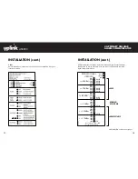
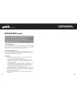
E. Connecting the 4530EX to the Alarm Panel
1. First, remove DC power from the 4530EX, and then proceed as follows:
2. Panel Connections
Connect the alarm panel’s telephone output to the 4530EX with an
appropriate cable. On the 4530EX’s side, the cable should use an RJ45 plug
and be connected into Jack JP3.
3. Output
The 4530EX has one relay output that can be used to activate an input on the
alarm panel or for other local purposes. Decide on how to use this output (see
section 6. Programming) then wire it from the terminal strip to the external panel
or device:
Output #1 Terminals: OUT1+ and OUT1-
The default state for this Output is as follows:
OUTPUT DEFAULT STATE
DEFAULT DEFINITION
#1
Configurable - normally
closed
Loss of cellular service
See Figure 2 as an example of how to connect the 4530EX to the alarm panel.
IMPORTANT: Make all of the connections to the 4530EX in the powered down state. Once
all of the connections have been established, turn power on.
(INSTALLATION continued next page)
ALARM PANEL
Host Panel/DC In
TO RJ31X
Orange (#2)
Note: To use Uplink Remote,
connect wires #3 and #6 to the
panel as indicated in the
4530EX 4G Primary
Alarm Communicator
Yellow (#6)
Blue (#7)
Black (#3)
1
2
3
4
Switch# Setting
Off
On
Function
Normal Operations
Load Defaults
Off
On
Off
On
Off
On
Allow OTA Config
Block OTA Config
Reserved
Normal Operations
Normal Operations
RSSI Measurements
IN1+
IN1-
OUT1+
OUT1-
Uplink Remote manual.
INSTALLATION (cont.)
FIGURE 2: Connections between the 4530EX and the Alarm Panel


