


18
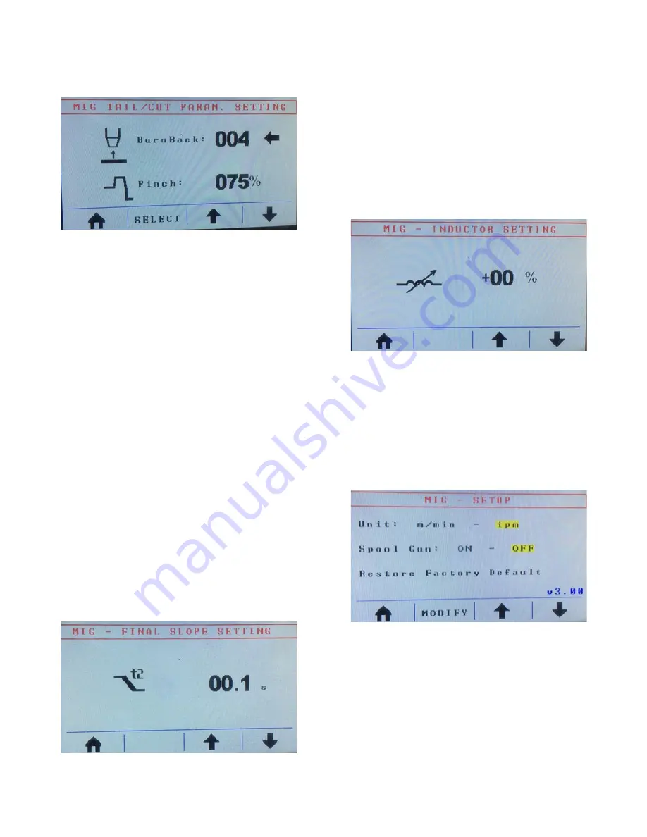
Fig. 16
To go to the next screen, press and release button
E
.
The new screen (
Fig. 16
) allows you to make
adjustments to what the wire does upon weld
completion. Burn back adjusts how long the wire
sticks out after you finish welding. A low number
allows the wire to stick out as it normally does on a
classic MIG welder, without any adjustments. The
higher the number, the shorter the stick out (
Attention:
High burn back numbers create the risk of burning the
wire back into the contact tip. We recommend starting
out with very low numbers
). Different wires react
differently. For example, aluminum reacts differently
than steel; when welding aluminum, set burn back to
004. The pinch function clips wire electrically. Right
before you finish the weld, the machine sends a burst
of current that shapes the end of the wire. Depending
on the setting, there might not be a ball on the end of
the wire that needs to be clipped off before re-striking
an arc. To set the pinch, push and release button
C
once, and then turn encoder
G
to the desired setting.
Different wire types need different settings. For
instance, flux-cored wire doesn’t need much pinch,
while aluminum wire tends to work well with 30% to
60% pinch, depending on the alloy and diameter (high
pinch rates, such as more than 75% pinch cause burn
backs near or into the tip, which causes damage to the
tip). Steel wire and 3/64” diameter 5554 aluminum
wire needs 100% pinch to get the desired result.
After adjusting the burn back and pinch, press and
release button
E
again to get to the next screen. This
screen (
Fig. 17
) allows you to adjust the slope down
setting for pulse welding. The slope down feature allows
you to fill the crater at the end of an aluminum weld or
allows you to neatly feather out a stainless steel weld.
On aluminum, set t2 between 3 and 5 seconds by turning
encoder
G
. After you release the trigger, the machine
still runs for the amount of time selected, but tapers
down automatically during the slope down time. The
tapering is visual in the arc and is also audible (the
frequency and the sound of the machine change). If no
slope down is desired, set t2 to 0.1 seconds.
Fig. 18
The slope down feature is only available in pulse
programs. Synergic, non-pulse programs have an option
to adjust inductance (
Fig. 18
). By turning encoder
G
,
you can adjust the inductance of the machine. Typically,
this feature is not available on transformer machines or
budget inverter machines. The inductance feature allows
you to set the arc characteristics from stiff/crisp to soft.
release button
C
(the little, left-pointing arrow will
move down from start speed to start time). Turning
encoder
G
now adjusts the start time.
Fig. 17
Fig. 19
You can access the final screen (
Fig. 19
) by pressing
and releasing button
E
once again. Options on the final
screen should not be adjusted by you unless previously
instructed by HTP America, Inc. technical service. In
this screen, the machine can be switched from Imperial
to Metric (which is preferred by many collision repair
shops). Also, if an optional spool gun is used on the
machine it needs to be activated here.
Summary of Contents for Pro Pulse 220 MTS
Page 5: ...5 Fig 1...
Page 13: ...13 Fig 3...
Page 26: ...26 Pro Pulse 220 MTS Wiring Diagram...


