


15
If you use a foot pedal, we recommend setting the
slope down time to 0.1 seconds.
You can adjust the slope down time by turning encoder
G
until the display shows the desir ed dur ation (
Fig.
7
).
Fig. 7
To get to the next screen, press and release button
E
.
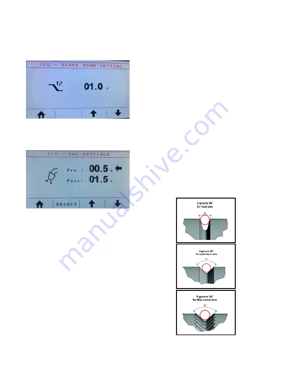
The next screen shows the gas flow options (
Fig. 8
).
Fig. 8
You can adjust the pre-flow gas setting by turning
encoder
G
. Pressing and releasing button
C
moves the
arrow from pre– to post-flow and turning encoder
G
now adjusts the post-flow gas setting.
We recommend a 5-10 second post-flow setting for
most TIG applications.
To Start the Arc
Touch the clean and freshly sharpened tungsten to the
clean metal of the work piece that you want to weld
and that you attached the ground clamp to. Now, press
and hold the torch switch, or depress the foot pedal
(just slightly), and lift the tungsten off the work piece
about 1/8”. The machine senses that the tungsten lifted
and initiates an arc. At this point, the weld can be
made. If you use a hand control or foot pedal, you can
vary the amperage during welding. When you finish, if
using a hand control, let go of the torch switch. The Pro
Pulse 220 MTS goes into slope down, and the arc
terminates by itself. If you use a foot pedal, gently lift
your foot off the pedal to extinguish the arc.
MIG Welding—General Information
MIG welding with the Pro Pulse 220 MTS can be done
three different ways: manual, synergic, and pulse. In
any case, the following things are critical to making
good welds:
Use the correct wire for the material being welded.
Use the correct gas, at the correct flow rate, for the
wire.
Use the drive roll with a groove that matches the
wire diameter chosen. There are different sizes and
shapes of drive rolls. For .023”, .024”, and .025”
diameter wire, use a drive roll marked 0.6;
for .030” wire, use a drive roll marked 0.8;
for .035” wire, use a drive roll marked 0.9 or 1.0;
for .045”, .047”, and 3/64” wire, use a drive roll
marked 1.2. (
Note: Drive rolls are reversible; there
are two different size grooves on the same drive
roll, and the marking has to face you
.) Also,
different materials require different drive roll
groove shapes. For instance, mild steel wire,
stainless steel wire, and silicon bronze wire
typically use a standard V shaped drive roll (
Fig.
9
). Softer aluminum wire uses a U shaped, or V90
degree, drive roll (
Fig. 10
). Flux-cored wire,
whether used with or without gas, and most hard-
faced wire requires the use of a knurled drive
roll—the little teeth provide extra traction on these
wires (
Fig. 11
).
Fig. 9
Fig. 10
Fig. 11
Summary of Contents for Pro Pulse 220 MTS
Page 5: ...5 Fig 1...
Page 13: ...13 Fig 3...
Page 26: ...26 Pro Pulse 220 MTS Wiring Diagram...


