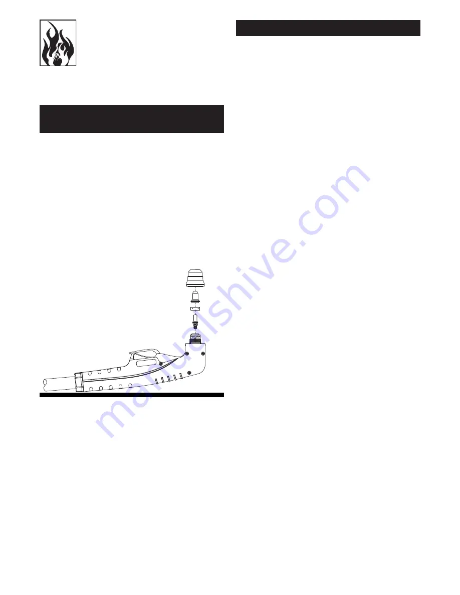
HTP MICROCUT 600 Owner'S Manual Download Page 13

 13

WORK 
TABLE

SHIELD CUP

CUTTING TIP

SWIRL RING

ELECTRODE

TORCH HEAD 

ASSEMBLY

Figure 7 PLASMA TORCH CONSUMABLE PARTS

TORCH CONSUMABLE PARTS 

SELECTION

CAUTION

Sparks from the cutting process can 
cause damage to coated, painted, and 
other surfaces such as glass, plastic and 
metal. 

NOTE

 Handle torch leads with care and protect 

them from damage.

To change the torch consumable parts use the 
following procedure: Position the torch with the 
shield cup facing upward to prevent these parts 
from falling out when the cup is removed.

Use:

-   .036 ø cutting tip to cut pieces more than .2 

inch thick (output current 30-40 Amp) 

-  .031 ø cutting tip to cut pieces more than .2 

inch thick (output current 20-30 Amp)

-  .025 ø cutting tip to cut pieces less than .2 

inch thick (output current 10-20 Amp) 

WARNING: Wait the torch has suffi

  ciently 

cooled before replacing torch parts.

1.  Unscrew and remove the shield cup from the 

Torch Head Assembly. 

2.  Remove the tip, swirl ring, and electrode. 
3.  Install the electrode, swirl ring, and tip. 
4.  Hand tighten the shield cup until it is seated 

on the torch head. If resistance is felt when 
installing the cup, check the threads before 
proceeding.

OPERATING FAULTS

During cutting operations performance faults 
may arise which are not caused by the plasma 
cutter but by other operational faults such as:

• Insuffi

  cient penetration :

too high cutting speed;
torch is too tilted;
piece is too thick;
cutting current too low;
torch parts are worn out;
non-genuine Manufacturer’s parts;

• 

Interruption of the cutting arc:

cutting speed too slow;
excessive distance between torch and 
workpiece;
AC line too low - reduce output current;
torch parts are worn out;
non-genuine Manufacturer’s parts;
work cable is disconnected;

• Excessive 

dross:

too low cutting speed (bottom dross);
too high cutting speed (top dross);
excessive distance between torch and 
workpiece;
cutting current too low;
torch parts are worn out;
non-genuine Manufacturer’s parts;

• 

Tilted cutting (not perpendicular):

torch position not correct;
asymmetric wear of nozzle hole and/or wrong; 

assemblage of the torch parts;

• 

Excessive wear of nozzle and electrodes:

air pressure too low;
exceeding system capability (material too thick);
contaminated air (humidity-oil);
excessive pilot arc arc ignitions in the air;
Improperly assembled torch;
torch tip contacting workpiece;
damaged or loose torch head components;
non-genuine Manufacturer’s parts.

Summary of Contents for MICROCUT 600

Page 1: ...HTP America Inc 180 Joey Drive Elk Grove Village IL 60007 TEL 847 357 0700 FAX 847 357 0744 MICROCUT 600 Owner s Manual...

Page 2: ...ssume for it any other liability in connection with the sale of its machines This warranty shall not apply to any cutting machine which has been repaired or altered by unau thorized service department...

Page 3: ...re to comply with these instructions could result in personal injury and or property damage RETAIN THESE INSTRUCTIONS FOR FUTURE REFE RENCE Note The following safety alert symbols identify important s...

Page 4: ...ssing Do not allow the unit to be connected to the power source or attempt to operate if the unit cables work area or power cord are exposed to any form of atmospheric precipitation or salt water spra...

Page 5: ...d slag can fly 35 feet and can pass through small cracks and openings If work and combustibles cannot be separated by a minimum of 35 feet protect against ignition with suitable snug fitting fire resi...

Page 6: ...ring air supplied respirators Do not heat metals coated with or that contain materials that produce toxic fumes such as galvanized steel unless the coating is removed Make certain the area is well ven...

Page 7: ...NG AND WEL DING PROCESS obtainable from the National Fire Protection Association 1 Batterymarch Park P O Box 9101 Quincy MA 02269 9101 Telephone 617 770 3000 Fax 617 770 0700 www nfpa org OSHA Standar...

Page 8: ...SPECIFICATIONS normally again However you should wait at least ten minutes after the thermal protector opens before resuming work You must do this even if the thermal protector resets itself before t...

Page 9: ...ac 4 RED LED CUTTING CURRENT Turns ON when torch is triggered Blinks quickly during 3 second safety pre flow prior to pilot arc ignition Blinks slowly if cutting arc is not initiated after 3 second pi...

Page 10: ...urn cable of the cutting current may endanger the safety system and give poor cutting results Do not make a ground connection on the piece which has to be removed TORCH CONNECTION WARNING BEFORE START...

Page 11: ...power to the system GROUND CABLE Check for a solid ground cable connection to the workpiece AUTOMATIC PURGE SYSTEM Place the ON OFF switch to the ON position The ON light will flicker momentarily as t...

Page 12: ...matically for 3 seconds To shut off the torch simply release the control switch When the switch is released a post flow will occur If the torch trigger is pressed during the post flow the pilot arc wi...

Page 13: ...lt when installing the cup check the threads before proceeding OPERATING FAULTS During cutting operations performance faults may arise which are not caused by the plasma cutter but by other operationa...

Page 14: ...lace immediately Electrode Replace electrode when crater settling on emitting surface is about 5 64 WARNING Before disassembling to the torch let it cool for at least the postgas period We recommend r...

Page 15: ...t least 72 5 PSI during purge or pre flow adjust air pressure to 65 PSI 2 Air filter or air line blocked torch blocked Replace filter cartridge Check that air line and torch leads are free of twists a...

Page 16: ...1 60002 TORCH HEAD 1 02 60003 ELECTRODE 1 03 60004 SWIRL RING 1 04 60025 TIP 025 10 20A 1 04 60031 TIP 031 20 30A 1 04 60036 TIP 036 30 40A 1 05 60005 SHIELD CUP 1 06 60008 HANDLE MICRO 1 TORCH PARTS...

Page 17: ...600226 COVER PANEL 1 11 21605040 CABLE CLAMP 1 11 21605041 NUT FOR CABLE CLAMP 1 12 20220120 INPUT CABLE 1 13 21600030 PLASTIC HANDLE 1 14 60180 PLASMA TORCH 1 15 21605039 CABLE CLAMP NUT 1 16 4321015...

Page 18: ...18 WIRING DIAGRAM...

Reviews: