LP-719 Rev. 000 Rel. 000 Date 6.25.20
75
1 P1
Insufficient circulation or missing water: Gradient T supply> 12.6 °F / sec
Warning
1 P2
Insufficient circulation or missing water: T supply - T return> 99 °F
Warning
1 P3
Inadequate circulation or missing water: T return - T supply> 18 °F
Warning
DHW Circuit
Reset?
2 01
Damaged or shorted DHW
temperature probe
Applicable to Combi models only.
1. Check DHW outlet temperature probe and wiring. Ensure connections are secure.
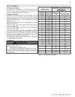
2. Check sensor resistance. If resistance does not match Table 33 - Sensor Temperature Resistance -
replace the sensor.
3. If problem persists, replace the main control.
NOTE:
When this error occurs, the controller references the boiler return temperature sensor instead
of the DHW outlet sensor and continues to function for both CH and DHW demands.
Warning
2 03
Storage temp. probe circuit
open / short circuit
Only applicable to Non-Combi boilers with DHW tank sensor. Check tank sensor wiring. If not using a
tank sensor, set parameter 2.2.8 = 2.
NOTE:
When this error occurs the appliance continues to meet CH demands.
Blocking
(Auto
Reset)
2 05
DHW In Probe Open Circuit (Solar temp. probe)
2 09
Storage overheating
(> 176 °F = on; <175 °F; off)
Check tank sensor and wiring. Replace if damaged.
NOTE:
When this error occurs the appliance will continue to operate for CH demands.
2 P2
Anti - Legionella function not completely finished
Warning
Internal PCB’s
Reset?
3 01
Display error Eeprom
Switch the boiler OFF and ON at the main electrical power supply. If the problem happens again
replace the main PCB.
Blocking
(Auto
Reset)
3 02
Communication error GP - GIU
Switch the boiler OFF and ON at the main electrical power supply. If the problem happens again:
1. Check the connection between the main PCB and the HMI
2. Replace the main PCB.
3 03
PCB internal error
Switch the boiler OFF and ON at the main electrical power supply. If the problem happens again
replace the main PCB.
3 04
Too many (> 5) resets in 15
minutes
Switch the boiler OFF and ON at the main electrical power supply.
Blocking
(Auto
Reset)
(1)
(1) Turn Off the Power to the Boiler
3 05
PCB internal error
Switch the boiler OFF and ON at the main electrical power supply. If the problem happens again
replace the main PCB.
Blocking
(Manual
Reset)
3 06
PCB internal error
Switch the boiler OFF and ON at the main electrical power supply. If the problem happens again
replace the main PCB.
3 07
PCB internal error
Switch the boiler OFF and ON at the main electrical power supply. If the problem happens again
replace the main PCB.
3 09
Gas relay check failed
Switch the boiler OFF and ON at the main electrical power supply. If the problem happens again
replace the main PCB.
3 P9
Sched. Maintenance-Call for
Service
Reset the error with the parameter 852
Warning
External P.C.B.’s
4 11
Room sensor circuit open or short circuit Zone 1
Blocking
(Auto
Reset)
4 12
Room sensor circuit open or short circuit Zone 2
4 13
Room sensor circuit open or short circuit Zone 3
4 30
Detected accessory wired to
BUS connection
If connecting an NTI zone controller to the BUS connection, ensure parameter 11.0.0 = 1.
Warning
4 31
Ignition and Detection
5 01
No flame detected (3 times)
Press the Reset button to clear the error code.
If Error happens again:
1. Monitor the gas pressure to the appliance while in operation. Ensure pressure is between 3.5 and
10.5” WC (Natural Gas), or between 8 and 13” WC for boilers converted to Propane (LP) operation.
2. Check gas valve wire. Ensure connection is secure.
3. Check flame detection sensor. Ensure connections are secure. Normal operating settings are more
than 2.5DC before ignition; less than 2.5DC after ignition.
4. Check igniter transformer for proper connection.
5. Clean the spark igniter with steel wool to remove oxides. Ensure proper separation (3-4 mm).
6. Replace the spark igniter if damaged.
7. Ensure that the flame is stable when lit.
8. If the problem persists, replace the main control.
Blocking
(Manual
Reset)
Display
Description
Possible Remedies
Error
Type


