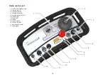
Control description - Control panel
1. Standby indicator - Power:
This lamp indicates the machine is in standby mode
with its systems activated. The position of the key in
the ignition switch (9) determines whether the grinder
is shut off or in standby mode and ready for use.
2. Overload indicator:
This lamp lights when the grinder is using too much
power when processing. Ignoring this warning lamp
will result in the power supply to the grinder being cut
via an overload protection device.
3. Communication error indicator - Com Error:
This lamp is lit when a communications error occurs
between the floor grinder and the radio control unit.
4. Radio control indicator - Radio Enabled:
When the “Radio On/Off” (5) knob is turned to the right
the indicator lamp lights. When the lamp is lit the ma-
chine is ready to be controlled via the radio control
unit. See description page .
5. Radio control On/Off:
When the switch for radio control “Radio On/Off” on
the grinder’s control panel is turned to the right, the
“Radio Enabled” lamp lights and the machine is now
ready to be controlled via the radio control unit.
Activating the radio control on the operator panel over-
rides the “Start/Stop” (7) and “Speed” (6) controls on this
panel. Only “On/Off” (5) and the emergency stop “EM-
stop” (8) are now active.
6. Adjustment of rotational speed of the grinding
head - Speed (Grinding Head Speed):
Use this knob to set an appropriate rotation speed
for the grinding head. This is only possible when the
grinding head is started via the “Start/Stop” knob (7).
7. Start/Stop of the rotation of the grinding head -
Start/Stop (Grinding Head):
Use this switch to start or stop the grinding head rota
-
tion. Use the “Speed” knob (6) to adjust the rotational
speed.
8. Emergency Stop - EM-Stop:
Only use the Emergency Stop switch, “EM-Stop” in
emergencies when immediate shutdown of the grind
-
er is necessary.
As long as the emergency stop switch “EM-Stop” is
pressed in, the machine cannot be started. Reset by
turning the emergency stop 45° so that the switch pops
out again. The machine is now ready to be restarted.
9. Ignition switch (Standby):
Turn the key in the ignition switch to the right to acti
-
vate the electrical system of the grinder. The machine
assumes standby mode and is ready for use.
Summary of Contents for 950 RX
Page 1: ...v 3...
Page 2: ......
Page 34: ...32 798 1347 1287 2047 2154 1338 1196 985 Technical data...
Page 47: ...45 29 1 2 3 4 5 6 7 8 9 10 11 12 13 14 15 16 17 18 19 20 21 22 23 24 25 26 27 28 30 31...
Page 49: ...47 2 3 4 5 6 7 8 9 10 12 13 14 15 16 17 19 20 21 22 23 1 18 11...
Page 53: ...51 1 2 3 1 4 5 6 7 8 9 10 11 12 13 14 15 3 2 3 2 16...


