background image

3

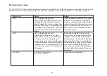
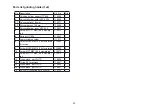
Electronic error codes cont.

Error code

Cause

Action

SCF

SCF = Short circuit on motor side

Due to a short circuit either in the motor or 

in the motor cable. May also be an earth 

fault.

Check the cabling and test the insulation 

in the motor if necessary. Test by loosen

-

ing the motor cable and starting the fre

-

quency converter to see if the error code 

arises. If it does, the error is in the fre

-

quency converter. If not, the cable or the 

motor is probably defective. 

tnF

tnF = Autotuning error

May arise if the motor has replaced a 

defective motor. The motor is outside the 

norms for what a converter can handle. 

Could also arise if the motor is defective.

Check the motor. Replace the motor with 

an original motor.

OLF

OLF = Overload motor

Tripped motor protection. Arises follow

-

ing long-term overload of the motor. The 

motor protection in the converter trips to 

protect the motor.

Reduce the speed of the grinder. The 

grinder runs too robustly. It takes around 8 

minutes before the grinder can be started 

again. The motor protection must cool 

down.

OSF

OSF = Overvoltage

Mains voltage too high or interference in 

the mains. May arise if large motors/ma

-

chines are started or shut down in the 

vicinity. May arise from non CE- marked 

equipment.

Measure the feed voltage. Change the 

terminal. Max feed voltage is 240V + 10%.

USF

USF = Undervoltage

Mains voltage too low. Results from many 

users in the mains. Temporary loss of volt

-

age Long and/or weak cables may cause 

this error. 

Change terminal or remove users from the 

mains. (Welds and suchlike cause these 

errors). Replace cable.

Summary of Contents for 950 RX

Page 1: ...v 3...

Page 2: ......

Page 3: ...g us the market leader within the field The new HTC 950 RX represents a milestone not just for HTC but also for the entire industry that was started with the launch of the very first professional grin...

Page 4: ...nformation HTC reserves the right to alter descriptions in this manual without prior notice This manual is protected by copyright and no part may be copied or in any way used without the express writt...

Page 5: ...e 12 Function description of machine components 13 1 Drive lock 13 2 Motor box drive 13 3 Electrical cabinet 13 4 Weight lock 13 5 Connection extractor 13 6 32A Connection elec 13 7 Control panel 13 8...

Page 6: ...ergency Stop EM Stop 15 9 Ignition switch Standby 15 Radio control unit 16 Description of controls Radio control unit 17 1 OFF ON Emergency stop 17 2 Steering control 17 3 Frequency button 17 4 Grindi...

Page 7: ...e operation easier 28 Maintenance 29 Cleaning the machine 29 Charging the grinder batteries 29 Charging the radio control unit batteries 29 Spare parts and service 31 Environment 31 Technical data 32...

Page 8: ...aterial damage as far as possible it is of the utmost importance that you carefully read and fully understand the texts that accompany these symbols There are also some practical tips marked with a sy...

Page 9: ...with the tools applied Be careful when replacing grinding tools as the tools and metal discs can be hot Disconnect the power supply from the machine when replacing the grinding tools Only lift the mac...

Page 10: ...nd serial number for your machine is shown on the machine plate This information is required when ordering spare parts for the grinder Use the space below to note the model number and serial number of...

Page 11: ...meets the various CE directives EMC directives and other possible requirements in the new procedures directives The HTC 950 RX grinder has CE marking in accordance with the Low Voltage Directive LVD...

Page 12: ...93 68 EEG Type of equipment Grinder Make HTC Trademark HTC 950 RX Serial number ___________________ Manufacturer HTC Sweden AB Box 69 SE 614 22 S derk ping Sweden The product has been CE marked in 200...

Page 13: ...nc tions and propulsion and steering A newly patented drive system with four grinding discs previously three gives the grinder a perfect balance Greater motor output of 15 kW Integrated system of weig...

Page 14: ...Control panel 13 Weight 2 Motor box drive 8 Handle 14 Grinding cover 3 Electrical cabinet 9 Handle locking 15 Water connection 4 Weight lock up position 10 Lifting eye 16 Weight lock down position 5 C...

Page 15: ...and breakers for operating the floor grinder along with control lamps indicating the status of the grinder See page 14 for a detailed description 8 Handle The handle can be locked in various positions...

Page 16: ...1 Standby indicator 4 Radio control indicator 7 Start Stop of grinding head rotation 2 Overload indicator 5 Radio control On Off 8 Emergency stop 3 Communication error indicator 6 Adjustment of rotat...

Page 17: ...lamp lights and the machine is now ready to be controlled via the radio control unit Activating the radio control on the operator panel over rides the Start Stop 7 and Speed 6 controls on this panel O...

Page 18: ...5 6 7 8 9 10 11 12 1 OFF ON Emergency stop 2 Steering control 3 Frequency button 4 Grinding head rpm 5 Grinding head OFF ON 6 Battery LED 7 Radio LED 8 Battery 9 Speed motion 10 Motion fwd rev 11 Adju...

Page 19: ...d rpm This potentiometer is used to adjust the rotation speed of the grinding head of the machine with the grinding tools 5 Grinding head OFF ON This switch starts or stops the rotation of the grindin...

Page 20: ...lted backwards when changing grinding tools Back position Always use when operating the grind er manually but can also be used when operating via radio control Picture 2 Depending on the type of work...

Page 21: ...m the motors by disconnecting the driv ing locks See pictures 1 and 2 Picture 1 Release the wheels from the motors by pulling the wheel locking pin straight out and then turning it 90 degrees see pict...

Page 22: ...floor If the weights are set to up position see picture 2 the centre of gravity is placed on the driving wheels instead This position for the weights applies when transporting the grinder and when it...

Page 23: ...th the grinding tools Also remember that the tools can be extremely hot following grinding work Picture 1 Fold the handle straight up and then set the weights to back position Put one foot against the...

Page 24: ...ng rubber hammer Move the grinding tool slightly tilted forwards down into the intended slots in the tool holder to mount Now push the tool forwards out from the centre of the tool holder see picture...

Page 25: ...tain equilibrium around the lifting eye See picture 1 Prepare to start Prior to start and operation the HTC 950 RX you should check that the grinder and any peripheral equipment are in tact Ensure tha...

Page 26: ...ards and turned using the motors that are positioned in the drive motor box see pos 2 page 12 In order for the motors to be able to drive the wheels the wheel locks must be protected between the wheel...

Page 27: ...Start up procedure Providing the points in the Prepare to start section on page 23 have been checked the following applies Assuming that all knobs on the grinder control panel are switched off Check t...

Page 28: ...ght the Ra dio Enabled LED lights up and the machine is ready to be controlled with the radio control unit Start routine Radio control 1 Release the Stop Emergency stop button 1 on the hand controller...

Page 29: ...the machine stopping This is how to change the frequency of the machine with the hand controller 1 Stop the machine as described under Stop routine radio control page 26 2 Hold down the Start radio co...

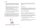
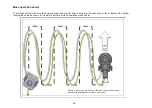
Page 30: ...rator and mains cable coming into the work area or line of travel of the grinder running the cable as shown in the picture below will make operation much easier Picture 1 By running the hose and cable...

Page 31: ...rious components caus ing damage We recommend the regular inspection of seals especially the seal by the upper belt See pos 26 and 30 on page 45 This seal should be inspected once every three months a...

Page 32: ...ed If the grinding holders oscillate or wobble considerably they are damaged Overhaul all grinding holders at the same time Check that the upper belt is intact Try to turn the large disk in any direct...

Page 33: ...ays state the model and serial number when you have queries about your grinder Environment The majority of components in HTC machines are made of recyclable metals or plastics The HTC 950 RX is fully...

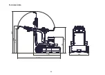
Page 34: ...32 798 1347 1287 2047 2154 1338 1196 985 Technical data...

Page 35: ...y propulsion Lead Battery radio unit Li Ion Frequency band Europe 868 MHz Frequency band USA 915 MHz Technical data Material HTC 950 RX Covers ABS plastic Chassis Galvanised steel Handle Plastic coate...

Page 36: ...uestion Can you work with and remotely control more than one HTC 950 RX at the same time in the same area without them interfering with each other Answer Yes theoretically up to 60 machines but in pra...

Page 37: ...nder will shut down for safety reasons To fix this restart or if necessary switch off the interfering equip ment Com error flashes on and off This could be quite normal if other radio signals in the r...

Page 38: ...motor and start the converter to see if the error remains Also see the point below If the error remains the converter will need a service OHF OHF Rapidly rising current A lower level of the same erro...

Page 39: ...he motor with an original motor OLF OLF Overload motor Tripped motor protection Arises follow ing long term overload of the motor The motor protection in the converter trips to protect the motor Reduc...

Page 40: ...is the case OPF OPF Motor phase failure Comes about if the motor contact is not properly connected or there is a gap The error can also be on the motor side if the contacts or the terminal block are...

Page 41: ...three levels of overload 1 OCF 2 OHF 3 OLF Things to remember The grinder will not start if the front back position is engaged when the power supply is applied Check the latest error code 1 Keep ESC...

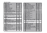
Page 42: ...2 24 Wheel HTC 950 110899 2 25 Adjustment bolt Lockable wheel 111036 2 26 Screw MC6S M8x20 8 8 zinc plated 310161 8 No Description Art No Qty 27 Washer BRB M8 310077 8 28 Gas spring complete HTC 950 1...

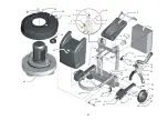
Page 43: ...41 1 2 3 4 5 7 8 9 10 11 12 13 14 15 16 17 18 20 19 22 23 24 25 26 28 27 29 30 31 32 33 42 21 34 35 36 37 38 39 40 41 43 45 46 44 47 48 49 50 51 6...

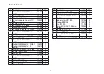
Page 44: ...knob 2 positions 111574 1 18 Nut Nylock M6 galvanised DIN985 310072 4 19 Fixing plate pump 111445 1 20 Hose large reinforced PVC 1 1 m 110130 1 21 Nut Nylock M8 galvanised DIN985 310067 2 No Descript...

Page 45: ...43 1 1 2 3 3 3 4 5 29 28 4 4 3 3 3 6 1 7 8 1 6 1 6 9 4 2 5 10 12 11 4 14 15 16 12 13 17 18 3 4 19 20 23 21 4 22 23 24 25 26 27 25 32 24 31 23 35 33 34 36 37 30 38 31 39...

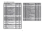
Page 46: ...4 2 Washer BRB M6 310012 4 3 Packing control panel 111166 1 4 Console instrument panel HTC 950 110990 1 5 Handle HTC 950 111033 1 6 Nut M6M M5 zinc plated 310193 4 7 Washer BRB 5 3x10x1 310194 4 8 Co...

Page 47: ...45 29 1 2 3 4 5 6 7 8 9 10 11 12 13 14 15 16 17 18 19 20 21 22 23 24 25 26 27 28 30 31...

Page 48: ...cer wheel locking HTC 950 111052 2 10 Ball bearing 61908 2RS1 111087 2 11 Sleeve wheel locking HTC 950 111050 2 12 Washer wheel locking HTC 950 111051 2 13 Washer BRB M6 310012 2 14 Screw MC6S M8x20 8...

Page 49: ...47 2 3 4 5 6 7 8 9 10 12 13 14 15 16 17 19 20 21 22 23 1 18 11...

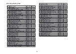
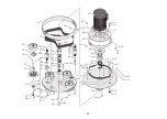
Page 50: ...207 2rs C3 110078 2 38 Circlip SGA 35 310038 2 39 Axle belt tensioner lower HTC 950 110932 2 40 Shaft HTC 950 110925 3 41 Lower Plate HTC 950 110911 1 42 Screw MC6S M8x25 zinc plated 310065 8 43 Nut l...

Page 51: ...9 15 16 10 11 12 13 14 15 16 17 18 19 20 21 22 23 24 25 26 28 27 29 30 31 32 33 34 35 36 37 38 39 41 42 44 45 46 47 48 52 51 50 49 53 54 55 56 57 58 59 60 61 62 63 64 65 66 67 69 68 71 70 72 73 75 76...

Page 52: ...T TT M6X16 8 8 zinc pla ted 310014 8 6 Spring HTC 950 110942 1 7 Lower grinding holder 111071 1 8 Screw MC6S M6X10 8 8 zinc plated B version 310005 2 9 Screw MC6S M6X16 8 8 zinc plated 310082 8 10 Scr...

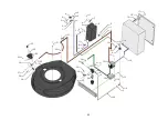
Page 53: ...51 1 2 3 1 4 5 6 7 8 9 10 11 12 13 14 15 3 2 3 2 16...

Page 54: ...52 Parts list electrical components No Description 1 Electrical socket 2 Control panel 3 Radio control 4 Connection motor...

Page 55: ...el 32A 380V N tkabel Kommunikationkabel mellan kontrollpanel och radios ndare Motorkabel Kabel f r matning av h ger drivmotor sett fr n kontrollpanel Kabel f r matning av v nster drivmotor sett fr n m...

Page 56: ...54 HTC Sweden AB Po Box 69 SE 614 22 S derk ping Sweden Tel 46 0 121 294 00 Fax 46 0 121 152 12 www htc sweden com...

Reviews: