background image


THT60 - THT70 


EN - 38

5.2.4 Camera menu 

In this section it is possible to carry out the following operations: 
 

¾

  Fixing the images on the display 

¾

  Saving the images on the micro SD card 

¾

  Carrying out voice annotations when saving the image 

¾

  Carrying out text annotations when saving the image 


5.2.4.1  Fixing the image on the display and saving 

An IR image on the display may be saved on the micro SD card inserted in the instrument, 
after it has been frozen on the display. Proceed as follows: 
 
1.  Insert the micro SD card into the relevant slot of the instrument. The icon “

” is shown 

in the top left-hand part of the display. 

2. Press the 

T

 (Trigger) key to freeze an IR image on the display. The symbol “ ” appears 

in the upper part of the display, the icon “

” appears in the lower part of the display 

and the icon “

” becomes fully light blue “

” (see Fig. 60 – right side). The same 

result is obtained by touching the icon “

” in the general menu and by touching the 

icon “

” (see Fig. 60 – left side). Touch the icon “

” and then the 

T

 key to exit the 

Hold function. 


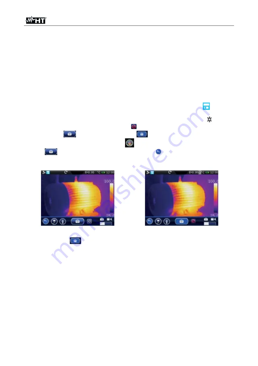
Fig. 60: Freezing the image on the display and saving 


3.  Touch the icon “

” or press the 

T

 key again to save the image on the display. The 

image is saved with the name ”YYMMDD_xxxxT” in which: “YY = Year”, “MM = Month”, 
“DD = Day” and “xxxx = progressive number of saving. This indication appears for a 
moment on the display. 


Summary of Contents for THT60

Page 1: ... Copyright HT ITALIA 2020 Release EN 2 00 24 03 2020 ENGLISH User manual ...

Page 2: ...ines 21 5 2 2 3 Setting of measuring areas 23 5 2 2 4 Setting the Measure Menu 25 5 2 2 5 Control parameters of temperature measurement 28 5 2 3 Image menu 30 5 2 3 1 Setting the display type 30 5 2 3 2 Setting the colour palette 32 5 2 3 3 Adjusting the image temperature 35 5 2 3 4 Setting the Isotherm function 37 5 2 4 Camera menu 38 5 2 4 1 Fixing the image on the display and saving 38 5 2 4 2 ...

Page 3: ...50 7 4 End of life 50 7 5 Accessories 50 7 5 1 Accessories provided 50 7 5 2 Optional accessories 50 8 TECHNICAL SPECIFICATIONS 51 8 1 Environment 52 8 1 1 Environmental conditions for use 52 9 SERVICE 53 9 1 Warranty conditions 53 9 2 Service 53 ...

Page 4: ...nd replaced with identical models when necessary x Check that the battery is correctly inserted x Check that the LCD display gives indications consistent with the function selected x Do not direct the instrument at very high intensity radiation sources e g the sun in order to prevent damaging the IR sensor x Prevent hits or strong vibrations in order to keep the instrument from damage x When bring...

Page 5: ...lyses Spots Lines Areas Isotherm x Automatic detection of hot cold spots of the image x Screening function for surface temperature rapid measurement x Storage of JPG images on external micro SD card x IR sensor resolution 160x120pxl THT60 384x288pxl THT70 x USB port for PC connection and image transfer x Voice and text annotations x IR MPEG4 video recording on micro SD card x Video and microphone ...

Page 6: ...ackaging contains all components indicated in 7 5 In case of discrepancy please contact the Dealer In case the instrument should be replaced please carefully follow the instructions given in 0 3 2 INSTRUMENT POWER SUPPLY The instrument is supplied by a 1x7 4V rechargeable Li ION battery and AC mains power supply which also provides for the recharge of the mentioned battery Both of these systems ar...

Page 7: ... NOMENCLATURE 4 1 INSTRUMENT DESCRIPTION Fig 1 Description of the instrument s backside CAPTION 1 Lens associated with the IR sensor 2 Trigger key T 3 LCD touch screen display 4 Function keys 5 Battery compartment cover ...

Page 8: ...THT60 THT70 EN 7 Fig 2 Description of the instruments front side CAPTION 6 Built in illuminator 7 Photo camera 8 Laser pointer 9 Lens locking releasing mechanism 10 Lens associated with the IR sensor ...

Page 9: ...ment body 13 Universal adapter for tripods 14 Lens protection cap Fig 4 Description of the instrument s side interfaces CAPTION 15 Video output 16 USB port 17 Audio input for connecting microphone headphones 18 Input for connecting AC adapter battery charger 19 Slot for micro SD card insertion ...

Page 10: ...nt also allows the display to automatically switch off after a selected time see 5 2 1 2 x The instrument may take approx 10s to switch off in case it is connected to the external power supply 4 2 2 Key Pressing the key allows showing hiding the icons of the instrument s main menu operation possible also by touching the display setting the value of the distance from the object in Fusion screens se...

Page 11: ...he IR image on the display and automatically opens the section for saving the image see The symbol is found in the top part of the display Press the T key again to save the image and quit the Hold status 4 2 7 Mounting of optional lens For the mounting of focal optional lens proceed as follows 1 Rotate the lens locking releasing mechanism see Fig 2 part 9 in counterclockwise from position to posit...

Page 12: ... of object emissivity Active HOLD function see 4 2 6 C Temperature measuring unit selected on the instrument see 5 2 1 1 Battery charge level indication see 7 2 12 00 Indication of the system s current time see 5 2 1 1 Level Indication of temperature levels of the IR image see 5 2 3 3 Palette Indication of colour palette see 5 2 3 2 M Auto HG Indication of image temperature adjustment mode see 5 2...

Page 13: ... 0 y 360 7 Touch the key to restore normal image view 8 Touch the OK key to quit the menu 5 1 3 Adjusting the distance of the object in Fusion screens In IR_MIX_VIS and VIS_MIX_IR display mode see 5 2 3 1 due to the different position of the lens and of the built in photo camera when the object is close to the lens the visible image tends to become bigger while the IR image tends to reduce When th...

Page 14: ...he Isotherm line tool Camera menu Æ defines the saving modes of IR images and videos Gallery menu Æ includes the gallery of the IR images saved in the micro SD card Video menu Æ includes the list of the IR videos saved in the micro SD card Settings menu Æ allows setting system parameters 5 2 1 Settings Menu By touching the icon the instrument enters the Setting menu in which it is possible to defi...

Page 15: ...s accuracy when measuring temperature Following options are available Single the value is displayed with one decimal figure Double the value is displayed with two decimal figures Setting the temperature measuring unit Touch the box Temp Unit to define the measuring unit used by the instrument when measuring temperature Available options are C F F 32 1 8x C K K C 273 15 Setting the distance measuri...

Page 16: ...real time on the display A very high level means an increased consumption of the internal battery 3 Touch OK to save your choice and exit the screen or Cancel to exit without saving Adjusting the automatic calibration time see 4 2 3 1 Touch the box Auto Calib The following screen appears on the instruments display Fig 14 Setting the automatic calibration time 2 Scroll the list of the available opt...

Page 17: ...h the screen or any other key to switch it on again 3 Touch OK to save your choice and exit the screen or Cancel to exit without saving Adjusting the instrument s Auto Power Off time 1 Touch the box Auto Power Off to activate deactivate and adjust the auto power off time of the instrument after a period of inactivity The following screen appears on the instrument s display Fig 16 Setting the instr...

Page 18: ...screen appears on the instrument s display Fig 18 Setting the image saving time 2 Touch the keys or to define both the numerical value of time with a resolution of 1 unit and the choice of Hours Minutes or Seconds By touching the numerical value field the instrument automatically opens a virtual keyboard see Fig 18 Right side in which it is possible to quickly enter any value Confirm with OK on th...

Page 19: ... choosing the desired time format 4 Touch the box set Time and the keys and to set current time 5 Touch OK to save your choice and exit the screen or Cancel to exit without saving 5 2 1 5 Information section This section contains the information relevant to the instrument such as model serial number production date and internal Firmware version In the lower part the space already used on the micro...

Page 20: ...select the modes which can be associated to each cursor see Fig 22 Following options which exclude one another are available Manual cursor freely managed by the user Max cursor associated to the hottest spot of the image Min cursor associated to the coldest spot of the image The selection is indicated by the icon on the display Fig 22 Measuring modes associated to cursors 3 In manual mode the curs...

Page 21: ...ighlighted in red and the symbols and to decrease or increase the value Keep the keys pressed for a quick selection of the values The measuring ranges are the following Emissivity Æ 0 01 y 1 00 Distance Æ 0m y 5000m Offset Æ 10 C y 10 C 9 For the parameter Emissivity it is possible to select the value according to an integrated table of the most common materials Touch the field of the parameter Th...

Page 22: ...ement Each line and its relevant cursor can be dragged to any point of the image displayed On the top left hand part of the display there are the labels L1 and L2 of the lines and the value of temperature associated to the cursors The line the cursor and the label of the selected line are displayed in red while they are white when they are fixed to the image Fig 26 Display of Measuring lines 2 Tou...

Page 23: ...e line To this purpose touch the field of the parameter highlighted in red and the symbols and to decrease or increase the value Keep the keys pressed for a quick selection of the values The measuring ranges are the following Emissivity Æ 0 01 y 1 00 Distance Æ 0m y 5000m Offset Æ 10 C y 10 C 8 For the parameter Emissivity it is possible to select the value according to an integrated table of the ...

Page 24: ...ly indicate the Maximum Minimum and Average temperature value of the internal spot within the area The positions of the Max and Min spots are indicated with the icons and on the image The area the label 1 2 and 3 and the Min Max Average values of the selected area are displayed in red while they appear in white when they are fixed to the image Fig 31 Display of Measuring area 2 Touch the icon to s...

Page 25: ...ea To this purpose touch the field of the parameter highlighted in red and the symbols and to decrease or increase the value Keep the keys pressed for a quick selection of the values The measuring ranges are the following Emissivity Æ 0 01 y 1 00 Distance Æ 0m y 5000m Offset Æ 10 C y 10 C 7 For the parameter Emissivity it is possible to select the value according to an integrated table of the most...

Page 26: ... parameters 1 Touch the item Global parameters The following screen appears on the instrument s display Fig 36 Setting the global parameters 2 Set the values of global parameters Emissivity Distance Offset see 5 2 2 5 and Screening see 5 3 1 relevant to the measuring object by touching the relevant fields see Fig 36 3 For the parameter Emissivity it is possible to select the value according to an ...

Page 27: ...Setting The following screen appears on the instrument s display Fig 39 Setting the general measuring parameters 2 The parameters whose field is included within the symbols and can be set Lens Æ Indication of the type of IR lens installed on the instrument This parameter is automatically modified by the instrument by changing the lens see 4 2 7 Possible options 7 5mm default 11mm 22mm 33mm THT60 2...

Page 28: ...y the user Target Æ It allows selecting one of the 3 measuring cursors see 5 2 2 1 found on the instrument to which to associate the alarm condition on temperature measurement Possible options Curs 1 Curs 2 or Curs 3 Mode Æ It allows defining the type of alarm threshold according to temperature measurement Possible options Lower Higher Same Temp Æ It allows setting the value of the temperature thr...

Page 29: ...77 Human skin 0 98 Sand 0 76 Slate 0 97 Non enameled silicone 0 75 Distilled water 0 96 Oxydized iron at 100 C 0 74 Smooth ice 0 96 C20A coating 0 73 Wet ground 0 95 Basalt 0 72 Carbon soot 0 95 Graphitized carbon at 500 C 0 71 Clean glass plate 0 94 Red rust 0 70 Paint oil 0 94 Very rusty iron 0 69 Red brick 0 75 Water 0 67 White paper 0 93 Black soil 0 66 Cement 0 97 White cement 0 65 Dry ground...

Page 30: ... associated with the colour palette must take see 5 2 3 3 In this case the levels ate increased or decreased by the quantity inserted in that field Offset Æ which can be set within the range 10 C y 10 0 C Parameter Distance This parameter identifies the distance between the thermal camera and the object to be measured In most of the applications the temperature levels associated to the colour pale...

Page 31: ...f visible image only see Fig 42 IR_FUSION_VIS Æ Display of visible image within the IR image with the possibility of choosing the position to the sides of the display see Fig 43 VIS_FUSION_IR Æ Display of IR image within the Visible image with the possibility of choosing the position to the sides of the display see Fig 44 IR_MIX_VIS Æ Display of visible image in the middle of the screen full scree...

Page 32: ...d display 2 In modes IR_FUSION_VIS and VIS_FUSION_IR touch the symbols and to select the position between the options BR at the bottom on the right BL at the bottom on the left TR at the top on the right and TL at the top on the left 3 In modes IR_MIX_VIS and VIS_MIX_IR touch the symbols and to select the dimensions of the internal frame in item Measurement between the options Half and Whole and t...

Page 33: ...ard palette 1 Touch the item Standard palette The following screen appears on the instrument s display Fig 47 Setting the standard palette 2 Scroll the entire length of the Table with your finger in order to find the desired option and activate the symbol Touch OK to confirm or Cancel to go back to the previous screen Notice the presence of the colours of the palette in the lower part of the displ...

Page 34: ...e 5 Touch the item Rename to change the name of the palette max 8 figures An internal virtual keyboard is shown on the display see Fig 49 Confirm the operation with OK 6 Touch the item Add to add further custom palettes see Fig 50 It is possible to add max 8 palettes further to the two available by default By touching the item Remove it is possible to remove custom palettes except for the two alre...

Page 35: ...ectrum and observing the resulting effect on the bar positioned at the top of the display see Fig 52 right side 11 Confirm the operation with OK or press Cancel to exit without saving and go back to the previous screen 12 Drag the 4 division markers of the temperature range along the bar until the desired intermediate temperature values are obtained see Fig 53 right side Fig 53 Customizing the use...

Page 36: ...omatically by the instrument as in Auto mode but in this case the areas of the image in which temperature values are very different from the values of adjacent areas are highlighted Manual M mode Æ the minimum and maximum temperature levels of the object framed on the display are manually set by the user who can associate if necessary a custom colour palette This mode particularly useful to clearl...

Page 37: ... with the colour palette until reaching the desired effect see Fig 57 Adjusting the levels is carried out with a fixed interval defined by the instrument and which cannot be modified and the colour palette becomes white Fig 57 Single adjusting of high and low level of temperature 6 Touch the icon for the simultaneous adjustment of both high and low level of temperature Touch the symbols and to car...

Page 38: ...shows the spots of the image with temperature between IsoMIn y IsoMax with colour defined by the user x Higher Æ the instrument shows the spots of the image with temperature higher than IsoMax with colour defined by the user x Lower Æ the instrument shows the spots of the image with temperature lower than IsoMin with colour defined by the user IsoMax Æ defines the value of maximum threshold which ...

Page 39: ...e icon is shown in the top left hand part of the display 2 Press the T Trigger key to freeze an IR image on the display The symbol appears in the upper part of the display the icon appears in the lower part of the display and the icon becomes fully light blue see Fig 60 right side The same result is obtained by touching the icon in the general menu and by touching the icon see Fig 60 left side Tou...

Page 40: ...lay 3 Insert the jack of the headphones provided into the instrument see Fig 4 Part 17 4 Touch the icon to start recording the voice annotation 5 Speak into the microphone found on the headphones connected to the instrument for the desired time 6 Touch the icon to stop recording The following screen appears see Fig 62 Left side Fig 62 Stopping a voice annotation 7 Touch the icon to save the voice ...

Page 41: ...Cancel key to exit without saving the comment 5 To see the text annotation again see 5 2 5 5 2 4 4 Recording IR videos The instrument allows recording and saving IR videos on the micro SD card as follows 1 Touch the icon in the general menu and move the icon to the right The following screen appears see Fig 64 Left side Fig 64 IR video recording 2 Insert eventually the jack of the headphones provi...

Page 42: ...resence of voice and text annotations saved with the image 4 Touch an image in the gallery to see it again The screen Fig 65 Right side is shown on the display The meaning of the symbols is the following and Æ allows switching from an image to the other Æ allows zooming in the image Press and hold the icon to continuously increase the zoom Touch the icon to exit the screen and restore normal displ...

Page 43: ...ing images as follows Touch the icon with the image recalled on the display see 5 2 5 Inside the gallery after making a selection as follows 1 Touch the icon Delete inside the image gallery The following screen see Fig 67 Right side is shown on the display Fig 67 Selecting and deleting images 2 Touch the single images or the icon Select all to select all images in the gallery The icon is shown on ...

Page 44: ...ol X The screen Fig 68 Right side is shown on the display The meaning of the symbols is the following Æ Play IR video Æ Stop IR video Æ Pause IR video Æ Adjust recording volume Æ Back to IR video gallery Æ Back to main menu 5 2 6 1 Deleting IR videos The instrument allows deleting IR videos as follows 1 Touch the icon Delete inside the IR video gallery The following screen see Fig 69 Right side is...

Page 45: ...t is switched on and continues during the thermal cameras normal operation during which the image freezes for a few seconds in order to eliminate offset errors The noise produced by the commutation of internal parts is not to be considered as a problem of the instrument 3 Before any measuring operation correctly focus the thermal camera in order to prevent having grossly inaccurate measurements an...

Page 46: ...In such situations in which an accurate temperature measurement is not strictly necessary emissivity value may be set to 1 see 5 2 2 5 it is not necessary to consider the objects surface its distance and the field of view However if accurate measures are required e g the temperature of an electric motor it is necessary to correctly set the parameters previously described in this manual 6 Correctly...

Page 47: ...utomatic measuring mode see 5 2 3 3 7 Perform the correct focusing of the subject on test see 5 1 1 8 Frame the subject on test at a recommended distance of 1m With subject temperature higher than the set alarm threshold value the following actions are performed by the instrument see Fig 73 right part The temperature value associated to the selected cursor and the limit threshold are shown with fl...

Page 48: ... micro SD card to a PC folder 5 5 VIDEO OUTPUT The video output available in the instrument see Fig 4 Part 15 enables displaying the IR image acquired on an external monitor or video recording device capable of managing PAL or NTSC systems To connect the instrument proceed as follows 1 Switch on the instrument 2 Touch the icon and setting the PAL or NTSC system see 5 2 1 1 3 Connect the instrument...

Page 49: ...CD ROM into the reader of the PC 2 Launch the file THTLink exe found inside the CD ROM and follow the guided installation procedure 6 3 MAIN CHARACTERISTICS OF THE THTLINK SOFTWARE With launched program the PC shows the following initial screen Fig 74 Starting screen of the THTLink software Main characteristics of the THTLink software Display of IR and visual images Insertion of advanced analysis ...

Page 50: ...as follows By connecting the instrument to the electric mains through the battery charger provided with the instrument Insert the battery into the recharging base and connect it to the electric mains CAUTION x The battery must not be removed from the instrument while recharging x Recharge the battery at room temperature avoiding too high or too low temperatures x When using the instrument for the ...

Page 51: ...ed of 7 5 ACCESSORIES 7 5 1 Accessories provided x Focal lens for IR measurements f 7 5mm THT60 x Focal lens for IR measurements f 22mm THT70 x Lens protection cap x BAT7X Æ Rechargeable Li ION battery 7 4V 2700mAh 2 pieces x A007X Æ AC DC 100 240V 12V adapter universal plugs x BRC7X Æ Battery recharging base x Micro SD card 8GB x Adapter for micro SD card x USB cable x RCA video cable x Set of he...

Page 52: ...Standard 10 Custom Laser pointer Class 2 in compliance with IEC 60825 1 Electronic zoom x1 x20 Image rotation 0 y 360 in steps of 1 Emissivity correction 0 01 1 00 in steps of 0 01 Measuring modes Automatic Manual Histogram Measuring functions corrections according to env temperature reflected temperature distance relative humidity offset Advanced analyses Spots 3 Lines 2 Areas 3 Isotherm Built in...

Page 53: ... Allowable relative humidity 10 RH 90 RH Mechanical protection IP65 in compliance with IEC 529 Drop test 2m 7ft Shock 25G in compliance with IEC60068 2 29 Vibrations 2G in compliance with IEC60068 2 6 This instrument complies with Directive EMC 2014 35 EU This instrument satisfies the requirements of European Directive 2011 65 EU RoHS and 2012 19 EU WEEE ...

Page 54: ... a consequence of improper packaging x Repairs which may become necessary as a consequence of interventions performed by unauthorized personnel x Modifications to the instrument performed without the manufacturers explicit authorization x Use not provided for in the instruments specifications or in the instruction manual The content of this manual cannot be reproduced in any form without the manuf...

Reviews: