background image

6.

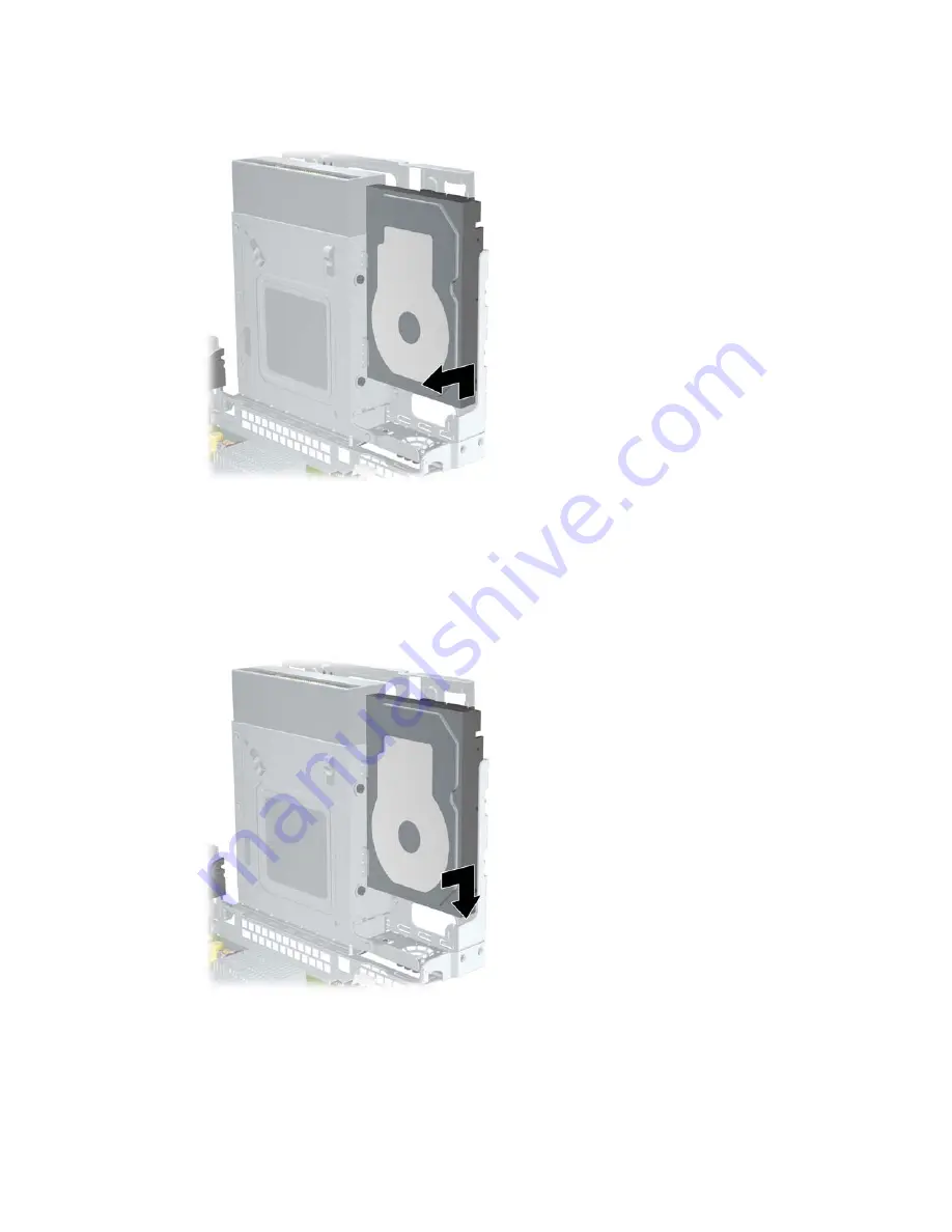
Slide the hard drive back approximately 1.3 cm (1/2 inch) and remove it from the drive cage.

Figure 6-42

  Removing the Hard Drive

To install a hard drive:

1.

Follow the procedure above to remove the old hard drive.

2.

Insert the hard drive “upside down.” Align the hard drive with the hard drive bay in the drive cage
so that the bottom of the hard drive is next to the optical drive compartment and the power and
data connectors are up. Slide the drive all the way down into the drive cage until it stops.

Figure 6-43

  Installing the Hard Drive

Drives

65

Summary of Contents for Rp3000 - Point of Sale System

Page 1: ...Service Reference Guide HP rp3000 Point of Sale ...

Page 2: ...cts and services Nothing herein should be construed as constituting an additional warranty HP shall not be liable for technical or editorial errors or omissions contained herein This document contains proprietary information that is protected by copyright No part of this document may be photocopied reproduced or translated to another language without the prior written consent of Hewlett Packard Co...

Page 3: ...ollow directions could result in bodily harm or loss of life CAUTION Text set off in this manner indicates that failure to follow directions could result in damage to equipment or loss of information NOTE Text set off in this manner provides important supplemental information iii ...

Page 4: ...iv About This Book ...

Page 5: ...r Setup Security 9 Computer Setup Power 11 Computer Setup Advanced 12 Recovering the Configuration Settings 15 3 Computer Diagnostic Features HP Insight Diagnostics 16 Accessing HP Insight Diagnostics 16 Survey Tab 17 Diagnose Tab 17 Test Tab 18 Status Tab 19 Log Tab 20 Help Tab 20 Saving and Printing Information in HP Insight Diagnostics 20 Downloading the Latest Version of HP Insight Diagnostics...

Page 6: ...uipment 28 Operating Guidelines 29 Routine Care 30 General Cleaning Safety Precautions 30 Cleaning the Computer Case 30 Cleaning the Keyboard 30 Cleaning the Monitor 31 Cleaning the Mouse 31 Service Considerations 31 Power Supply Fan 31 Tools and Software Requirements 31 Screws 32 Cables and Connectors 32 Hard Drives 32 Lithium Coin Cell Battery 33 6 Removal and Replacement Procedures Preparation ...

Page 7: ...l Drive 62 Primary 3 5 inch Internal Hard Drive 64 Chassis Fan 67 Power Switch LED Assembly 67 Modem some models 68 Optical Drive Sensor 69 Power Supply 70 System Board 71 Battery 73 Appendix A Connector Pin Assignments Keyboard 75 Mouse 75 Ethernet RJ 45 76 RJ 11 76 Serial Interface Powered and Non Powered 76 USB 77 Powered USB 77 Line in Audio 77 Line out Audio 77 Monitor 78 24 Pin Power 78 SATA...

Page 8: ...roblems 98 Solving Hard Drive Problems 99 Solving Display Problems 101 Solving Audio Problems 105 Solving Printer Problems 107 Solving Keyboard and Mouse Problems 108 Solving Hardware Installation Problems 109 Solving Network Problems 111 Solving Memory Problems 114 Solving Processor Problems 115 Solving Optical Drive Problems 115 Solving USB Flash Drive Problems 119 Solving Internet Access Proble...

Page 9: ...allation CAUTION Once the automatic installation has begun DO NOT TURN OFF THE COMPUTER UNTIL THE PROCESS IS COMPLETE Turning off the computer during the installation process may damage the software that runs the computer or prevent its proper installation NOTE If the computer shipped with more than one operating system language on the hard drive the installation process could take up to 60 minute...

Page 10: ...osoft Windows XP The HP Backup and Recovery Manager included with Microsoft Windows Vista is a more limited version Check for updates by clicking Software Driver Downloads link at http www hp com Systems shipped without a Microsoft operating system may not include HP Backup and Recovery Manager The HP Backup and Recovery Manager is an easy to use versatile application that allows you to back up an...

Page 11: ...ecovery Manager Manual NOTE You can order a Recovery Disc Set from HP by calling the HP support center Go to the following Web site select your region and click the Technical support after you buy link under the Call HP heading to obtain the support center telephone number for your region http welcome hp com country us en wwcontact_us html HP Backup and Recovery Manager 3 ...

Page 12: ...s displayed each time the system is turned on or restarted Enter the Asset Tag or property identification number assigned by the company to this computer Enable the power on password prompt during system restarts warm boots as well as during power on Establish a setup password that controls access to Computer Setup F10 Utility and the settings described in this section Secure integrated I O functi...

Page 13: ...ant then press Enter To return to the Computer Setup Utilities menu press Esc 6 To apply and save changes select File Save Changes and Exit If you have made changes that you do not want applied select Ignore Changes and Exit To reset to factory settings or previously saved default settings some models select Apply Defaults and Exit This option will restore the original factory system defaults CAUT...

Page 14: ...p Save to Removable Media Saves system configuration including CMOS to a USB flash media device or a diskette like device a storage device set to emulate a diskette drive Restore from Removable Media Restores system configuration from a USB flash media device or a diskette like device Default Setup Save Current Settings as Default Saves the current system configuration settings as the default Rest...

Page 15: ... translation mode to be used for the device This enables the BIOS to access disks partitioned and formatted on other systems and may be necessary for users of older versions of UNIX e g SCO UNIX version 3 2 Options are Automatic Bit Shift LBA Assisted User and Off NOTE If User is selected for the Translation Mode you can specify the parameters logical cylinders heads and sectors per track used by ...

Page 16: ...TE This selection will only appear when at least one drive capable of performing the DPS self tests is attached to the system Boot Order Allows you to Specify the order in which attached devices such as a USB flash media device hard drive optical drive or Broadcom Ethernet Controller are checked for a bootable operating system image Each device on the list may be individually excluded from or incl...

Page 17: ... or setup password is set Allows you to Lock legacy resources appears if a setup password is set Enable disable network server mode appears if a power on password is set Specify whether the password is required for warm boot Ctrl Alt Delete appears if a power on password is set Enable Disable Setup Browse Mode appears if a setup password is set allows viewing but not changing the F10 Setup Options...

Page 18: ... Documentation and Diagnostics DVD for more information OS Security some models Data Execution Prevention some models enable disable Helps prevent OS security breaches NOTE An OS Security selection is in effect only if the processor and operating system being used comprehend and utilize the security feature Setup Security Level Provides a method to allow end users limited access to change specifie...

Page 19: ... a pause of 2 seconds green LED i e repeated cycles of 3 blinks and a pause S4 4 blinks at 1Hz 50 duty cycle followed by a pause of 2 seconds green LED i e repeated cycles of 4 blinks and a pause S5 LED is off If this feature is disabled S4 and S5 both have the LED off S1 no longer supported and S3 use 1 blink per second Hardware Power Management S5 Maximum Power Savings some models Enable Disable...

Page 20: ...Computer Setup Advanced Table 2 6 Computer Setup Advanced for advanced users Option Heading 12 Chapter 2 Computer Setup F10 Utility ...

Page 21: ...le disable Enabling this feature will cause the system to display a message before loading option ROMs This feature is supported on some models only Remote wakeup boot source remote server local hard drive After Power Loss off on previous state If set to Off the computer remains powered off when power is restored If set to On the computer automatically powers on as soon as power is restored If set...

Page 22: ...of the computer to Wake on LAN from suspend or hibernation but will prevent it from waking from S5 via the network It does not affect operation of the network connection while the computer is on If a network connection is not required completely disable the network controller NIC by using the arrow left and right keys to select the Security Device Security menu Set the Network Controller option to...

Page 23: ...tings to a a USB flash media device or a diskette like device a storage device set to emulate a diskette drive and save the diskette or device for possible future use To restore the configuration insert the USB flash media device or a diskette like device a storage device set to emulate a diskette drive with the saved configuration and perform the Restore from Removable Media command with the Comp...

Page 24: ...nded after installing or connecting a new device You should run tests save the test results and print them so that you have printed reports available before placing a call to the Customer Support Center NOTE Third party devices may not be detected by HP Insight Diagnostics Accessing HP Insight Diagnostics You must boot to the Documentation and Diagnostics DVD as described in the steps below to acc...

Page 25: ... connected to the computer Memory Shows information about all memory in the computer This includes memory slots on the system board and any memory modules installed Miscellaneous Shows HP Insight Diagnostics version information computer configuration memory CMOS information system board data and system management BIOS data Storage Shows information about storage media connected to the computer Thi...

Page 26: ...f a logical volume NOTE Smart Array Drive Diagnosis has the unique capability of identifying multiple disk drives in a single volume that are functioning normally but should be replaced To diagnose a logical volume 1 Click the Diagnose tab 2 Under Smart Array Drive Diagnosis click to expand Storage 3 Select the logical volumes to diagnose and click the Diagnose button 4 The test status of the logi...

Page 27: ... all devices 6 Click the Begin Testing button at the bottom right corner of the screen to start the test The Status tab which allows you to monitor the progress of the test is automatically displayed during the testing process When the test is complete the Status tab shows whether the device passed or failed 7 If errors are found go to the Log tab and click the Error Log to display more detailed i...

Page 28: ...st The Error Code provides a numerical code for the failure The error codes are defined in the Help tab The Clear Error Log button will clear the contents of the Error Log Help Tab The Help tab contains an HP Insight Diagnostics tab an Error Codes tab and a Test Components tab The HP Insight Diagnostics tab contains help topics and includes search and index features The Error Codes tab provides a ...

Page 29: ... the Software To protect software from loss or damage you should keep a backup copy of all system software applications and related files stored on the hard drive See the operating system or backup utility documentation for instructions on making backup copies of data files Restoring the Software The system software can be restored to the original state that they were when you purchased the comput...

Page 30: ...f files and folders operates in Windows The second PC Recovery requires a reboot to the Recovery Partition or from the Recovery Disc Set To reboot to the Recovery Partition press F11 at startup when you see the message Press F11 for Emergency Recovery 22 Chapter 3 Computer Diagnostic Features ...

Page 31: ...ower cable 15 Maximum data cable length 39 37 in 100 cm Data interface voltage differential 400 700 mV Drive voltages 3 3 V 5 V 12 V Jumpers for configuring drive N A Data transfer rate 3 0 Gb s SATA connectors on the system board are color coded to make identification easier SATA Identification Color Port Attachment Sequence Primary channel device 0 Dark blue SATA 0 1 Primary channel device 1 Lig...

Page 32: ... grounds and 4 transmit receive pins Pin Number Usage Device Plug Host Plug P1 Ground Ground Ground P2 A Transmit data Receive data P3 A Transmit data Receive data P4 Ground Ground Ground P5 B Receive data Transmit data P6 B Receive data Transmit data P7 Ground Ground Ground P2 and P3 differential signal pair P5 and P6 differential signal pair SATA Power Cable Pin Usage Notes Pin Usage Notes P1 V3...

Page 33: ...used in the computer determines the maximum usable size of a drive partition A drive partition is the largest segment of a drive that may be properly accessed by the operating system A single hard drive may therefore be subdivided into a number of unique drive partitions in order to make use of all of its space Because of the differences in the way that drive sizes are calculated the size reported...

Page 34: ...hapter is essential for proper service CAUTION When the computer is plugged into an AC power source voltage is always applied to the system board You must disconnect the power cord from the power source before opening the computer to prevent system board or component damage Chassis Designations rp3000 Figure 5 1 rp3000 26 Chapter 5 Identifying the Chassis Routine Care and Disassembly Preparation ...

Page 35: ...7 500 V 3 000 V 400 V 400 V 15 000 V 5 000 V 800 V 700 V 35 000 V 12 000 V 6 000 V 2 000 V Removing DIPs from vinyl tray Removing DIPs from Styrofoam Removing bubble pack from PCB Packing PCBs in foam lined box 2 000 V 3 500 V 7 000 V 5 000 V 4 000 V 5 000 V 20 000 V 11 000 V 11 500 V 14 500 V 26 500 V 21 000 V These are then multi packaged inside plastic tubes trays or Styrofoam NOTE 700 volts ca...

Page 36: ...the Work Area To prevent static damage at the work area use the following precautions Cover the work surface with approved static dissipative material Provide a wrist strap connected to the work surface and properly grounded tools and equipment Use static dissipative mats foot straps or air ionizers to give added protection Handle electrostatic sensitive components parts and assemblies by the case...

Page 37: ... the computer by blocking any vents or air intakes Do not place the keyboard with the keyboard feet down directly against the front of the desktop unit as this also restricts airflow Occasionally clean the air vents on all vented sides of the computer Lint dust and other foreign matter can block the vents and limit the airflow Be sure to unplug the computer before cleaning the air vents Never oper...

Page 38: ...bborn stains use isopropyl rubbing alcohol No rinsing is needed as the alcohol will evaporate quickly and not leave a residue After cleaning always wipe the unit with a clean lint free cloth Occasionally clean the air vents on the computer Lint and other foreign matter can block the vents and limit the airflow Cleaning the Keyboard Follow all safety precautions in General Cleaning Safety Precautio...

Page 39: ...r is turned off Clean the mouse ball by first removing the retaining plate and the ball from the housing Pull out any debris from the ball socket and wipe the ball with a clean dry cloth before reassembly To clean the mouse body follow the procedures in Cleaning the Computer Case on page 30 Service Considerations Listed below are some of the considerations that you should keep in mind during the d...

Page 40: ... snagged by parts being removed or replaced CAUTION When servicing this computer ensure that cables are placed in their proper location during the reassembly process Improper cable placement can damage the computer Hard Drives Handle hard drives as delicate precision components avoiding all physical shock and vibration This applies to failed drives as well as replacement spares If a drive must be ...

Page 41: ...There is a risk of fire and chemical burn if the battery is handled improperly Do not disassemble crush puncture short external contacts dispose in water or fire or expose it to temperatures higher than 140ºF 60ºC Do not attempt to recharge the battery NOTE Batteries battery packs and accumulators should not be disposed of together with the general household waste In order to forward them to recyc...

Page 42: ...m the computer 5 Turn off the computer and any peripheral devices that are connected to it CAUTION Turn off the computer before disconnecting any cables Regardless of the power on state voltage is always present on the system board as long as the system is plugged into an active AC outlet In some systems the cooling fan is on even when the computer is in the Standby or Suspend modes The power cord...

Page 43: ... following security devices are used to prevent unauthorized access to the internal components of the computer and or secure the computer to a fixed object Cable Lock Figure 6 1 Installing a Cable Lock External Security Devices 35 ...

Page 44: ... 2 Installing a Padlock HP Business PC Security Lock 1 Fasten the security cable by looping it around a stationary object Figure 6 3 Securing the Cable to a Fixed Object 36 Chapter 6 Removal and Replacement Procedures ...

Page 45: ...e cables that you want to secure through the lock Figure 6 4 Threading the Peripheral Device Cables 3 Screw the lock to the chassis using the screw provided Figure 6 5 Attaching the Lock to the Chassis External Security Devices 37 ...

Page 46: ... computer for disassembly Preparation for Disassembly on page 34 2 Remove the two screws on the rear of the computer 1 that secure the cover to the computer chassis 3 Slide the computer cover forward about 1 3 cm inch then lift it off the unit 2 Figure 6 7 Removing the Computer Cover To install the computer cover reverse the removal procedure NOTE When removing the cover be careful not to damage t...

Page 47: ...e the computer cover Computer Cover on page 38 3 Push outward on the two retaining tabs that hold the bezel blank in place 1 then pull the blank inward to remove it 2 Figure 6 8 Removing a Bezel Blank 4 Replace the computer cover To install a bezel blank reverse the removal procedure Bezel Blank 39 ...

Page 48: ... bend can break the internal wires Never bend a SATA data cable tighter than a 30 mm 1 18 in radius Never crease a SATA data cable Do not rely on components like the drive cage power supply or computer cover to push cables down into the chassis Always position the cables to lay properly by themselves When removing the power supply power cables from the connector on the system board always follow t...

Page 49: ...ard P7 Powered USB port expansion card P6 1st SATA Hard drive P5 Optical drive P4 Cable PCA Designator Hard drive SATA 0 Dark Blue Optical drive SATA 1 White Serial port 5V 12V COM 2 Chassis fan CHFAN Front power button LED and Optical drive sensor left two pins PB LED PCIe X1 riser connector PCIEX1RISER PCI riser connector PCIRISER 24 pin power connector PWR Cable Management 41 ...

Page 50: ... the DDR2 SDRAM DIMMs must be industry standard 240 pin unbuffered PC2 5300 667 MHz compliant 1 8 volt DDR2 SDRAM DIMMs The DDR2 SDRAM DIMMs must also support CAS latency 4 and 5 for DDR2 667 MHz contain the mandatory JEDEC SPD information In addition the computer supports 256Mbit 512Mbit and 1Gbit non ECC memory technologies single sided and double sided DIMMs DIMMs constructed with x8 and x16 DD...

Page 51: ...memory modules or system board If you see an LED light on the system board voltage is still present The memory module sockets have gold plated metal contacts When upgrading the memory it is important to use memory modules with gold plated metal contacts to prevent corrosion and or oxidation resulting from having incompatible metals in contact with each other Static electricity can damage the elect...

Page 52: ...touching 5 Open both latches of the memory module socket 1 and insert the memory module into the socket 2 NOTE A memory module can be installed in only one way Match the notch on the module with the tab on the memory socket 6 Push the module down into the socket ensuring that the module is fully inserted and properly seated Make sure the latches are in the closed position 3 Figure 6 12 Installing ...

Page 53: ...he computer has either a full height PCI expansion slot 1 or a full height PCI Express x1 expansion slot 2 depending on the model NOTE The maximum length supported for a PCI card or a PCI Express x1 card is 16 76 cm 6 6 inches Figure 6 13 Expansion Slot Locations Installing and Removing a PCI Card or PCI Express x1 Card You can install one full height PCI expansion card or one full height PCI Expr...

Page 54: ...moving the Slot Cover Screw 4 Remove the expansion slot cover or the existing expansion card a If you are installing an expansion card in a vacant socket slide the expansion slot cover straight out from the side of the chassis Figure 6 15 Removing an Expansion Card Slot Cover 46 Chapter 6 Removal and Replacement Procedures ...

Page 55: ... are not installing a new expansion card install an expansion slot cover to close the open slot CAUTION After removing an expansion card you must replace it with a new card or expansion slot cover for proper cooling of internal components during operation 7 To install a new expansion card align the bracket on the expansion card with the open slot on the rear of the chassis and press the card strai...

Page 56: ...ility Guide on the Documentation and Diagnostics DVD for instructions about using Computer Setup PCI Riser Card Cage Assembly The computer may have a PCI riser card cage installed To remove the cage as well as the card in the cage 1 Prepare the computer for disassembly Preparation for Disassembly on page 34 2 Remove the computer cover Computer Cover on page 38 3 Position the computer with the rear...

Page 57: ...er card to the riser bracket 1 and then remove the card from the bracket 2 Figure 6 20 Removing the card from the riser card cage To install the card cage and PCI riser card reverse the removal procedure When installing a card into the riser card cage you must properly install the card in the two bridges on the top of the bracket to avoid damage to the card Figure 6 21 Inserting a card into the ri...

Page 58: ... same time Figure 6 22 PoweredUSB Ports The 24 volt PoweredUSB connector 1 and the 12 volt PoweredUSB connector 2 are keyed differently as a precaution to prevent connection errors Figure 6 23 24 volt PoweredUSB Connector and 12 volt PoweredUSB Connector To remove or install a PoweredUSB expansion card 1 Prepare the computer for disassembly Preparation for Disassembly on page 34 2 Remove the compu...

Page 59: ...reverse the installation procedures NOTE If there is a panel covering the opening for the ports on the rear of the chassis you must remove the panel If a ReadyBoost module is installed you must remove it in order to plug in the Powered USB expansion card You may need to remove the power cable from the clamp on the chassis see following image so that it will reach the power connector on the card US...

Page 60: ...dels have a powered serial port expansion card installed that supplies two additional powered serial ports COM 3 and COM 4 Figure 6 25 Powered Serial Ports Item Description Supports 5V 12V 1 COM 1 Yes Yes 2 COM 2 Yes Yes 3 COM 3 some models Yes Yes 4 COM 4 some models Yes Yes 52 Chapter 6 Removal and Replacement Procedures ...

Page 61: ...Sale System computer can be configured as standard non powered serial ports or powered serial ports Some Point of Sale devices use a powered serial port If the serial port is configured as a powered port devices that support a powered serial interface do not require an external power source NOTE The computer ships with all serial ports configured in standard serial mode by default unless the power...

Page 62: ...COM 1 2 P17 COM 2 The serial port jumpers on the powered serial port expansion card are located as shown in the following illustration Figure 6 28 Powered Serial Port Expansion Card Jumper Locations Item Jumper Port Name 1 J4 COM 3 2 J5 COM 4 54 Chapter 6 Removal and Replacement Procedures ...

Page 63: ...guration a Raise the drive cage to the upright position b Place jumpers and jumper wires on the appropriate pins for COM 1 1 and COM 2 2 Figure 6 29 COM 1 and COM 2 Jumpers c Return the drive cage to the down position 4 If you are changing the Powered Serial Port Expansion Card COM 3 or COM 4 serial port configuration a Locate the Powered Serial Port Expansion Card in the expansion card slot Power...

Page 64: ...until the connectors pull free from the socket 2 Be sure not to scrape the card against the other components Figure 6 30 Removing the Powered Serial Port Expansion Card c Place jumpers and jumper wires on the appropriate pins for COM 3 1 and COM 4 2 Figure 6 31 COM 3 and COM 4 Jumpers 56 Chapter 6 Removal and Replacement Procedures ...

Page 65: ...ot Figure 6 32 Installing the Powered Serial Port Expansion Card e Connect the data cable to the riser card 1 and the expansion card 2 Connect the power cable to the expansion card 3 Figure 6 33 Connecting Data and Power Cables to the Powered Serial Port Expansion Card 5 Replace the computer cover 6 If the serial ports are configured in powered mode connect the powered Point of Sale device HP offe...

Page 66: ...ever you must first order the Powered Serial card AV KH887AA option before selecting this AV since there are only 2 serial ports on the rp3000 Adding the powered serial card provides a total of 4 serial ports AV GH656AV can then be selected so all four serial ports are configured for power Below is a diagram showing the jumper settings for each of these optional preconfigured AV numbers CAUTION Al...

Page 67: ...f one another CAUTION The DSUB shell in GND so when the ports are configured for power it is possible to short power to GND if something comes in contact with the shell and pin These AV s include COM port cover to help prevent this AVs Description GH655AV Service Preconfig 2x PWRD RS232 5V 12V GH656AV Service Preconfig 4x PWRD RS232 5V 12V Powered Serial Ports Removal and Installation 59 ...

Page 68: ...odels To verify the type size and capacity of the storage devices installed in the computer run Computer Setup Refer to the Computer Setup F10 Utility Guide on the Documentation and Diagnostics DVD for more information Installing and Removing Drives When installing additional drives follow these guidelines The primary Serial ATA SATA hard drive must be connected to the dark blue SATA connector on ...

Page 69: ...drive shut down the operating system properly turn off the computer and unplug the power cord Do not remove a drive while the computer is on or in standby mode Before handling a drive ensure that you are discharged of static electricity While handling a drive avoid touching the connector Handle a drive carefully do not drop it Do not use excessive force when inserting a drive Avoid exposing a hard...

Page 70: ... on page 34 2 Remove the computer cover Computer Cover on page 38 3 Raise the drive cage to the upright position 4 Disconnect the power cable 1 and data cable 2 from the rear of the optical drive Figure 6 36 Disconnecting the Optical Drive Power and Data Cables 5 Remove the four screws that secure the drive to the drive cage 1 and then slide the drive forward out of the drive bay 2 Figure 6 37 Rem...

Page 71: ... into the optical drive bay 1 and secure it in place with the four retainer screws 2 Figure 6 38 Installing the Optical Drive 4 Connect the power cable 1 and data cable 2 to the rear of the optical drive Figure 6 39 Connecting the Optical Drive Power and Data Cables CAUTION Never crease or bend a SATA data cable tighter than a 30 mm 1 18 in radius A sharp bend can break the internal wires 5 Connec...

Page 72: ...ver Computer Cover on page 38 3 Raise the drive cage to the upright position 4 Disconnect the data cable 1 and power cable 2 from the back of the primary hard drive Figure 6 40 Disconnecting the Hard Drive Data and Power Cables 5 Remove the four screws on top of the drive cage that secure the hard drive in the bay Figure 6 41 Removing the Hard Drive Retainer Screws 64 Chapter 6 Removal and Replace...

Page 73: ...ure above to remove the old hard drive 2 Insert the hard drive upside down Align the hard drive with the hard drive bay in the drive cage so that the bottom of the hard drive is next to the optical drive compartment and the power and data connectors are up Slide the drive all the way down into the drive cage until it stops Figure 6 43 Installing the Hard Drive Drives 65 ...

Page 74: ...s 4 Connect the data cable 1 and power cable 2 to the back of the primary hard drive NOTE The data cable must be connected to the dark blue connector labeled SATA 0 on the system board to avoid any hard drive performance problems Figure 6 45 Connecting the Hard Drive Data and Power Cables CAUTION Never crease or bend a SATA data cable tighter than a 30 mm 1 18 in radius A sharp bend can break the ...

Page 75: ...er Computer Cover on page 38 3 Position the computer with the rear facing toward you 4 Disconnect the fan control cable from the system board The connector is labeled CHFAN 5 Remove the two screws that secure the fan to the chassis tilt the top of the fan towards the inside of the chassis and then lift it out of the chassis Figure 6 46 Removing the Chassis Fan To install the chassis fan reverse th...

Page 76: ...rom the chassis To reinstall the power switch LED assembly reverse the removal procedure Modem some models 1 Prepare the computer for disassembly Preparation for Disassembly on page 34 2 Remove the computer cover Computer Cover on page 38 3 Position the computer with the rear facing toward you 4 Raise the drive cage to its upright position 5 Remove the two screws that secure the modem to the syste...

Page 77: ...assis Then press downward on the assembly until it snaps into place Optical Drive Sensor 1 Prepare the computer for disassembly Preparation for Disassembly on page 34 2 Remove the computer cover Computer Cover on page 38 CAUTION To reduce risk of damage to optical door sensor make sure you closely follow the computer cover removal instructions 3 Position the computer with the front facing toward y...

Page 78: ...from the computer and or the AC outlet before opening the computer 1 Prepare the computer for disassembly Preparation for Disassembly on page 34 2 Remove the computer cover Computer Cover on page 38 3 Position the computer with the rear facing toward you 4 Remove the riser card cage PCI Riser Card Cage Assembly on page 48 5 Rotate the drive cage up 6 Disconnect the power cables from all of the dri...

Page 79: ... are properly positioned so they are not cut by the drive cage System Board 1 Prepare the computer for disassembly Preparation for Disassembly on page 34 2 Remove the computer cover Computer Cover on page 38 3 Position the computer with the rear facing toward you 4 Rotate the drive cage to its full upright position 5 Remove the expansion board installed on the system board Expansion Cards on page ...

Page 80: ... and out of the chassis Figure 6 53 Removing the System Board To install the system board reverse the removal procedure CAUTION When reconnecting the cables it is important that they be positioned so they do not interfere with the rotation of the drive cage or power supply 72 Chapter 6 Removal and Replacement Procedures ...

Page 81: ...uide on the Documentation and Diagnostics DVD for information on backing up the CMOS settings Static electricity can damage the electronic components of the computer or optional equipment Before beginning these procedures ensure that you are discharged of static electricity by briefly touching a grounded metal object NOTE The lifetime of the lithium battery can be extended by plugging the computer...

Page 82: ...Battery 7 Return the drive cage to the down position 8 Replace the computer cover 9 Plug in the computer and turn on power to the computer 10 Reset the date and time your passwords and any special system setups using Computer Setup Refer to the Computer Setup F10 Utility Guide on the Documentation and Diagnostics DVD 11 Lock any security devices that were disengaged when the computer cover was rem...

Page 83: ...er and workstation connectors Some of these connectors may not be used on the product being serviced Keyboard Connector and Icon Pin Signal 1 2 3 Data Unused Ground 4 5 6 5 VDC Clock Unused Mouse Connector and Icon Pin Signal 1 2 3 Data Unused Ground 4 5 6 5 VDC Clock Unused Keyboard 75 ...

Page 84: ...Icon Pin Signal 1 2 3 4 5 6 Unused Tip Ring Unused Unused Unused Serial Interface Powered and Non Powered Connector and Icon Pin Signal 1 2 3 Carrier Detect 5V 12V if powered Receive Data Transmit Data 4 5 6 Data Terminal Ready Signal Ground Data Set Ready 7 8 9 Request to Send Clear to Send Ring Indicator 5V 12V if powered 76 Appendix A Connector Pin Assignments ...

Page 85: ...1 2 3 4 5 VDC Data Data Ground Right side 12V 24V 3A 72W 2 5A 30W Line in Audio Connector and Icon 1 8 miniphone Pin Signal 1 2 3 1 Tip 2 Ring 3 Shield Audio_In_Left Audio_In_Right Ground Line out Audio Connector and Icon 1 8 miniphone Pin Signal 1 2 3 1 Tip 2 Ring 3 Shield Audio_Out_Left Audio_Out_Right Ground USB 77 ...

Page 86: ...und Ground Ground Ground 13 14 15 Horizontal Sync Vertical Sync DDC Serial Clock 24 Pin Power Connector 24 12 13 1 Front Pin Signal Pin Signal Pin Signal Pin Signal 1 2 3 4 5 6 3 3V 3 3V GND 5V GND 5V 7 8 9 10 11 12 GND POK 5 Vaux 12V 12V 3 3V 13 14 15 16 17 18 3 3V 12V GND PSON GND GND 19 20 21 22 23 24 GND open 5V 5V 5V GND 78 Appendix A Connector Pin Assignments ...

Page 87: ...d x16 PCI Express Connector Pin A Pin Signal Pin Signal Pin Signal Pin Signal Pin Signal 1 2 3 4 5 PRSNT1 12V 12V GND JTAG2 6 7 8 9 10 JTAG3 JTAG4 JTAG5 3 3V 3 3V 11 12 13 14 15 PERST GND REFCLK REFCLK GND 16 17 18 19 20 PERp0 PERn0 GND RSVD GND 21 22 23 24 25 PERp1 PERn1 GND GND PERp2 26 27 28 29 30 PERn 2 GND GND PERp3 PERn3 31 32 33 34 35 GND RSVD RSVD GND PERp4 36 37 38 39 40 PERn4 GND GND PER...

Page 88: ... in the next table NOTE x1 PCI Express uses pins 1 18 x4 PCI Express uses pins 1 32 x8 PCI Express uses pins 1 49 x16 PCI Express uses pins 1 8 PCI Express Pin B x1 x4 x8 and x16 PCI Express Connector Pin B Pin Signal Pin Signal Pin Signal Pin Signal Pin Signal 1 2 3 4 5 12V 12V RSVD GND SMCLK 6 7 8 9 10 SMDAT GND 3 3 V JTAG1 3 3vAux 11 12 13 14 15 WAKE RSVD GND PETp0 PETn0 16 17 18 19 20 GND GND ...

Page 89: ...ND PETp9 PETn9 56 57 58 59 60 GND GND PETp10 PETn10 GND 61 62 63 64 65 GND PETp11 PETn11 GND GND 66 67 68 69 70 PETp12 PETn12 GND GND PETp13 71 72 73 74 75 PETn13 GND GND PETp14 PETn14 76 77 78 79 80 GND GND PETp15 PETn15 GND 81 82 PRSNT2 RSVD Pin A information is in the previous table NOTE x1 PCI Express uses pins 1 18 x4 PCI Express uses pins 1 32 x8 PCI Express uses pins 1 49 x16 PCI Express us...

Page 90: ...ncy responsible for evaluation in the country where the power cord set will be installed 2 The power cord set must have a minimum current capacity of 10A 7A Japan only and a nominal voltage rating of 125 or 250 volts AC as required by each country s power system 3 The diameter of the wire must be a minimum of 0 75 mm2 or 18AWG and the length of the cord must be between 1 8 m 6 feet and 3 6 m 12 fe...

Page 91: ...d set fittings appliance coupler and wall plug must bear the certification mark of the agency responsible for evaluation in the country where it will be used 2 The flexible cord must be Type SVT or equivalent No 18 AWG 3 conductor The wall plug must be a two pole grounding type with a NEMA 5 15P 15A 125V or NEMA 6 15P 15A 250V configuration 3 Appliance coupler flexible cord and wall plug must bear...

Page 92: ... during POST press any key except F10 or F12 The default mode is POST Message Disabled The speed at which the computer loads the operating system and the extent to which it is tested are determined by the POST mode selection Quick Boot is a fast startup process that does not run all of the system level tests such as the memory test Full Boot runs all of the ROM based system tests and takes longer ...

Page 93: ... Space for Option ROMs Recently added PCI expansion card contains an option ROM too large to download during POST 1 If a PCI expansion card was recently added remove it to see if the problem remains 2 In Computer Setup set Advanced Device Options NIC PXE Option ROM Download to DISABLE to prevent PXE option ROM for the internal NIC from being downloaded during POST to free more memory for an expans...

Page 94: ...emory Error RAM failure 1 Run Computer Setup or Windows utilities 2 Ensure memory modules are correctly installed 3 Verify proper memory module type 4 Remove and replace the identified faulty memory module s 5 If the error persists after replacing memory modules replace the system board 213 Incompatible Memory Module in Memory Socket s X X A memory module in memory socket identified in the error m...

Page 95: ...est BIOS image 512 Chassis Fan not Detected Chassis fan is not connected or may have malfunctioned 1 Reseat chassis fan 2 Reseat fan cable 3 Replace chassis fan 514 Chassis Fan not Detected Chassis fan is not connected or may have malfunctioned 1 Reseat chassis fan 2 Reseat fan cable 3 Replace chassis fan 1720 SMART Hard Drive Detects Imminent Failure Hard drive is about to fail Some hard drives h...

Page 96: ...ausing a problem Run Computer Setup and Diagnostic utilities Remove third party graphics card to see if the problem goes away Network Server Mode Active and No Keyboard Attached Keyboard failure while Network Server Mode enabled 1 Reconnect keyboard with computer turned off 2 Check connector for bent or missing pins 3 Ensure that none of the keys are depressed 4 Replace keyboard Parity Check 2 Par...

Page 97: ...e some models only or normal Suspend mode None required Press any key or move the mouse to wake the computer Red Power LED flashes two times once every second followed by a two second pause Beeps stop after fifth iteration but LEDs continue until problem is solved 2 Processor thermal protection activated A fan may be blocked or not turning OR The heatsink is not properly attached to the processor ...

Page 98: ...stem board For systems with integrated graphics replace the system board Red Power LED flashes seven times once every second followed by a two second pause Beeps stop after fifth iteration but LEDs continue until problem is solved 7 System board failure ROM detected failure prior to video Replace the system board Red Power LED flashes eight times once every second followed by a two second pause Be...

Page 99: ...ry the following 1 Replace the system board OR Press and hold the power button for less than 4 seconds If the hard drive LED does not turn on green then 1 Check that the unit is plugged into a working AC outlet 2 Open hood and check that the power button harness is properly connected to the system board 3 Check that the power supply cable is properly connected to the system board 4 Check to see if...

Page 100: ...ty Refer to Computer Diagnostic Features on page 16 for more information Run the Drive Protection System DPS Self Test in Computer Setup Refer to the Computer Setup F10 Utility Guide for more information Check the Power LED on the front of the computer to see if it is flashing red The flashing lights are error codes that will help you diagnose the problem Refer to Appendix A POST Error Messages on...

Page 101: ...Backup and Recovery Manager CAUTION Restoring the system will erase all data on the hard drive Be sure to back up all data files before running the restore process NOTE For sales information and warranty upgrades Care Packs call your local authorized service provider or dealer Helpful Hints If you encounter problems with the computer monitor or software see the following list of general suggestion...

Page 102: ...stem other than the factory installed operating system check to be sure that it is supported on the system If the system has multiple video sources embedded PCI or PCI Express adapters installed embedded video on some models only and a single monitor the monitor must be plugged into the monitor connector on the source selected as the primary VGA adapter During boot the other monitor connectors are...

Page 103: ... 2 Disconnect the power cord from the electrical outlet Computer will not respond to USB keyboard or mouse Cause Solution Computer is in standby mode To resume from standby mode press the power button CAUTION When attempting to resume from standby mode do not hold down the power button for more than four seconds Otherwise the computer will shut down and you will lose any unsaved data System has lo...

Page 104: ...efragment hard drive Program previously accessed did not release reserved memory back to the system Restart the computer Virus resident on the hard drive Run virus protection program Too many applications running 1 Close unnecessary applications to free up memory Some applications run in the background and can be closed by right clicking on their corresponding icons in the task tray To prevent the...

Page 105: ...ss and hold the power button for less than 4 seconds If the hard drive LED turns green then 1 Remove the expansion cards one at a time until the LED on the system board turns on 2 Replace the system board OR Press and hold the power button for less than 4 seconds If the hard drive LED does not turn on green then 1 Check that the unit is plugged into a working AC outlet 2 Open hood and check that t...

Page 106: ...mputer powered off automatically and the Power LED flashes Red two times once every second followed by a two second pause and the computer beeps two times Beeps stop after fifth iteration but LEDs continue flashing Cause Solution Processor thermal protection activated A fan may be blocked or not turning OR The heatsink is not properly attached to the processor 1 Ensure that the computer air vents ...

Page 107: ...ard drive error occurs Cause Solution Hard disk has bad sectors or has failed 1 In Microsoft Windows XP right click Start click Explore and select a drive Select File Properties Tools Under Error checking click Check Now In Microsoft Windows Vista right click Start click Explore and right click on a drive Select Properties then select the Tools tab Under Error checking click Check Now 2 Use a util...

Page 108: ...rmat using fdisk If NTFS formatting use a third party reader to evaluate the drive If FAT32 formatting the hard drive cannot be accessed System files missing or not properly installed 1 Insert a bootable CD or USB device and restart the computer 2 Check the hard drive format using Fdisk If NTFS formatting use a third party reader to evaluate the drive If FAT32 formatting the hard drive cannot be a...

Page 109: ...ress the power button again Solving Display Problems If you encounter display problems see the documentation that came with the monitor and the common causes and solutions listed in the following table Table D 4 Solving Display Problems Blank screen no video Cause Solution Monitor is not turned on and the monitor light is not on Turn on the monitor and check that the monitor light is on Bad monito...

Page 110: ...ick the Display icon and select the Settings tab 4 Use the sliding control to reset the resolution Blank screen and the power LED flashes Red five times once every second followed by a two second pause and the computer beeps five times Beeps stop after fifth iteration but LEDs continue flashing Cause Solution Pre video memory error 1 Reseat DIMMs Power on the system 2 Replace DIMMs one at a time t...

Page 111: ...ry video or requested resolution cannot be set Cause Solution If the graphics controller was upgraded the correct graphics drivers may not be loaded Install the video drivers included in the upgrade kit Monitor is not capable of displaying requested resolution Change requested resolution Graphics card is bad Replace the graphics card The picture is broken up rolls jitters or flashes Cause Solution...

Page 112: ...settings to a supported setting then restart the computer so that the new settings take effect Vibrating or rattling noise coming from inside a CRT monitor when powered on Cause Solution Monitor degaussing coil has been activated None It is normal for the degaussing coil to be activated when the monitor is powered on Clicking noise coming from inside a CRT monitor Cause Solution Electronic relays ...

Page 113: ...articular symbol Use the Character Map to locate and select the appropriate symbol Click Start All Programs Accessories System Tools Character Map You can copy the symbol from the Character Map into a document Solving Audio Problems If the computer has audio features and you encounter audio problems see the common causes and solutions listed in the following table Table D 5 Solving Audio Problems ...

Page 114: ...ght click on the CD DVD device and select Properties 4 On the Properties tab make sure Enable digital CD audio for this CD ROM device is checked Devices connected to the line out connector mute the internal speaker Turn on and use external speakers if connected or disconnect external speakers Volume is muted 1 From the Control Panel program click Sound Speech and Audio Devices then click Sounds an...

Page 115: ...not have made the connection to the printer Make the proper network connections to the printer Printer may have failed Run printer self test Printer will not turn on Cause Solution The cables may not be connected properly Reconnect all cables and check the power cord and electrical outlet Printer prints garbled information Cause Solution The correct printer driver for the application is not instal...

Page 116: ...your computer using the mouse and then restart the computer Keyboard needs repairs See the Worldwide Limited Warranty for terms and conditions Wireless device error 1 Check the software if available for device status 2 Check replace device batteries 3 Reset receiver and keyboard Computer is in standby mode Press the power button to resume from standby mode CAUTION When attempting to resume from st...

Page 117: ...2 Check replace device batteries 3 Reset receiver and mouse Computer is in standby mode Press the power button to resume from standby mode CAUTION When attempting to resume from standby mode do not hold down the power button for more than four seconds Otherwise the computer will shut down and you will lose any unsaved data Mouse will only move vertically horizontally or movement is jerky Cause Sol...

Page 118: ...he computer to integrate the device with the computer system When the system advised you of changes to the configuration you did not accept them Reboot the computer and follow the instructions for accepting the changes A plug and play board may not automatically configure when added if the default configuration conflicts with other devices Use Device Manager to deselect the automatic settings for ...

Page 119: ...cable is not seated properly or is bad or system board is bad For systems with a graphics card 1 Reseat the graphics card Power on the system 2 Replace the graphics card 3 Replace the system board For systems with integrated graphics replace the system board Power LED flashes Red ten times once every second followed by a two second pause and the computer beeps ten times Beeps stop after fifth iter...

Page 120: ...system via Device Manager Incorrect network driver Check the network controller documentation for the correct driver or obtain the latest driver from the manufacturer s Web site Network status link light never flashes NOTE The network status light is supposed to flash when there is network activity Cause Solution No active network is detected Check cabling and network equipment for proper connecti...

Page 121: ...col is installed The network controller is not configured for this computer Select the Network icon in the Control Panel and configure the network controller Network controller stopped working when an expansion board was added to the computer Cause Solution Network controller interrupt is shared with an expansion board Under the Computer Setup Advanced menu change the resource settings for the boa...

Page 122: ...avoid damage to the DIMMs or the system board you must unplug the computer power cord before attempting to reseat install or remove a DIMM For those systems that support ECC memory HP does not support mixing ECC and non ECC memory Otherwise the computer will not boot the operating system Table D 11 Solving Memory Problems System will not boot or does not function properly after installing addition...

Page 123: ...Cause Solution Memory is installed incorrectly or is bad 1 Reseat DIMMs Power on the system 2 Replace DIMMs one at a time to isolate the faulty module 3 Replace third party memory with HP memory 4 Replace the system board Solving Processor Problems If you encounter processor problems common causes and solutions are listed in the following table Table D 12 Solving Processor Problems Poor performanc...

Page 124: ...dware Installation Problems on page 109 section If the system still does not recognize the new device check to see if the device is listed within Computer Setup If it is listed the probable cause is a driver problem If it is not listed the probable cause is a hardware problem If this is a newly installed drive run the Computer Setup utility and try adding a POST delay under Advanced Power On Optio...

Page 125: ...and let Windows detect the CD or DVD driver Recording or copying CDs is difficult or impossible Cause Solution Wrong or poor quality media type 1 Try using a slower speed when recording 2 Verify that you are using the correct media for the drive 3 Try a different brand of media Quality varies widely between manufacturers Computer boots too slow after removing an optical drive Cause Solution The sy...

Page 126: ...g door that covers the optical drive will not open Cause Solution The sliding door is locked Use the provided key to unlock the door then slide the door down 118 Appendix D Troubleshooting Without Diagnostics ...

Page 127: ...was not properly seated before power up Ensure the device is fully inserted into the USB port before applying power to the system System will not boot from USB flash drive Cause Solution Boot order is not correct Run the Computer Setup utility and change boot sequence in Storage Boot Order Removable Media Boot is disabled in the Computer Setup utility Run the Computer Setup utility and enable boot...

Page 128: ...e cable LED light on the front of the cable DSL modem will be on The CAT5 UTP cable is disconnected Connect the CAT5 UTP cable between the cable modem and the computers s RJ 45 connector If the connection is good the PC LED light on the front of the cable DSL modem will be on IP address is not configured properly Contact your ISP for the correct IP address Cookies are corrupted A cookie is a small...

Page 129: ...k on System 4 In the Tasks list select Device Manager 5 Double click Modems 6 Double click Agere Systems PCI SV92PP Soft Modem 7 On the General tab click Diagnostics 8 Click Query Modem A Success response indicates the modem is connected and working properly Solving Software Problems Most software problems occur as a result of the following The application was not installed or configured correctly...

Page 130: ...maged Restore the files from the Recovery Disc Set or backups you created in HP Backup and Recovery Manager Illegal Operation has Occurred error message is displayed Cause Solution Software being used is not Microsoft certified for your version of Windows Verify that the software is certified by Microsoft for your version of Windows see program packaging for this information Configuration files ar...

Page 131: ...t Maximum rate of change is 10 C Hr The upper limit may be limited by the type and number of options installed Heat Dissipation Maximum Typical idle 785 BTU hr 150 BTU hr 169 kg cal hr 38 kg cal hr Power Supply Operating Voltage Range1 Rated Voltage Range Rated Line Frequency 115V 90 264 VAC 100 240 VAC 50 60 Hz 230V 90 264 VAC 100 240 VAC 50 60 Hz Power Output 150 W 150 W Rated Input Current maxi...

Page 132: ...m board 41 connector pin assignments 75 country power cord set requirements 83 Customer Support 92 122 D diagnostics utility 16 DIMMs See memory disassembly preparation SFF 34 drive SFF optical drive removal and replacement 62 drive positions SFF 60 E electrostatic discharge ESD preventing damage 27 error codes 84 89 messages 85 ethernet RJ 45 pin assignments 76 expansion slot cover removing 46 re...

Page 133: ...lation 94 Internet access 120 keyboard 108 memory 114 monitor 101 mouse 108 network 111 power 98 printer 107 processor 115 software 121 USB flash drive 119 processor problems 115 R Recovery Disc Set 21 removal and replacement battery 73 chassis fan 67 fan 67 LED assembly 67 modem 68 optical drive sensor 69 power supply 70 power switch LED assembly 67 SFF computer cover 38 SFF optical drive 62 syst...

Page 134: ...nt 71 SATA connectors 23 T tamper proof screws tool 32 temperature control 29 tools servicing 31 Torx T15 screwdriver 31 U unlocking computer cover 35 USB flash drive problems 119 USB pin assignments 77 V ventilation proper 29 W Wake on LAN feature 112 Web site HP recycling programs 73 126 Index ...

Reviews: