background image


Removal and replacement procedures  63 

3.


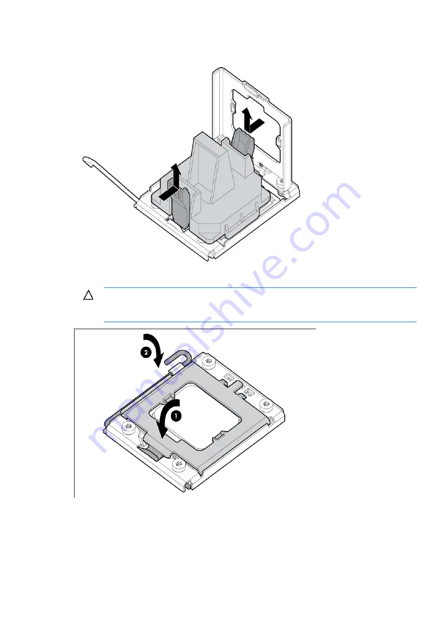
Press and hold the tabs on the processor installation tool to separate it from the processor, and then 

remove the tool. 


4.


Close the processor socket retaining bracket and the processor locking lever. 


CAUTION: 

 Be sure to close the processor socket retaining bracket before closing the processor 

locking lever. The lever should close without resistance. Forcing the lever closed can damage the 

processor and socket, requiring system board replacement. 


5.


Install the heatsink. 

All manuals and user guides at all-guides.com

Summary of Contents for PROLIANT ML350 G6

Page 1: ...s you are qualified in the servicing of computer equipment and trained in recognizing hazards in products with hazardous energy levels and are familiar with weight and stability precautions for rack installations Part Number 513502 007 February 2011 Edition 7 All manuals and user guides at all guides com a l l g u i d e s c o m ...

Page 2: ... statements accompanying such products and services Nothing herein should be construed as constituting an additional warranty HP shall not be liable for technical or editorial errors or omissions contained herein Microsoft and Windows are U S registered trademarks of Microsoft Corporation Intel and Xeon are trademarks of Intel Corporation in the U S and other countries All manuals and user guides ...

Page 3: ...ffle 33 Fan blank 34 Fan 34 Power supply blank 35 Hot plug power supply 36 SAS hard drive blank 36 SAS SATA hard drive 37 Hard drive cages 37 Standard hard drive cage 38 Optional eight bay SFF hard drive cage 38 Optional two bay LFF hard drive cage 40 Standard hard drive cage backplane 42 Expansion slot cover 43 Expansion board 44 Media bay blank 45 Battery backed write cache procedures 46 Battery...

Page 4: ...nents 78 Front panel LEDs and buttons 79 Rear panel components 80 Rear panel LEDs and buttons 81 System board components 82 System board LEDs 84 System maintenance switch 85 NMI functionality 85 DIMM identification 86 SAS SATA device numbers 87 SAS and SATA hard drive LEDs 88 SAS and SATA hard drive LED combinations 89 Battery pack LEDs 90 FBWC module LEDs 91 Fan locations and configurations 92 Op...

Page 5: ...e telephone HP specifies in the materials shipped with a replacement CSR part whether a defective part must be returned to HP In cases where it is required to return the defective part to HP you must ship the defective part back to HP within a defined period of time normally five 5 business days The defective part must be returned with the associated documentation in the provided shipping material...

Page 6: ...nsporteur à utiliser Pour plus d informations sur le programme CSR de HP contactez votre Mainteneur Agrée local Pour plus d informations sur ce programme en Amérique du Nord consultez le site Web HP http www hp com go selfrepair Service de garantie pièces seules Votre garantie limitée HP peut inclure un service de garantie pièces seules Dans ce cas les pièces de rechange fournies par HP ne sont pa...

Page 7: ...urzeiten zu minimieren und höhere Flexibilität beim Austausch defekter Bauteile zu ermöglichen Wenn HP oder ein HP Servicepartner bei der Diagnose feststellt dass das Produkt mithilfe eines CSR Teils repariert werden kann sendet Ihnen HP dieses Bauteil zum Austausch direkt zu CSR Teile werden in zwei Kategorien unterteilt Zwingend Teile für die das Customer Self Repair Verfahren zwingend vorgegebe...

Page 8: ...mponentes para los que la reparación por parte del usuario es obligatoria Si solicita a HP que realice la sustitución de estos componentes tendrá que hacerse cargo de los gastos de desplazamiento y de mano de obra de dicho servicio Opcional componentes para los que la reparación por parte del usuario es opcional Estos componentes también están diseñados para que puedan ser reparados por el usuario...

Page 9: ...erplicht Onderdelen waarvoor reparatie door de klant verplicht is Als u HP verzoekt deze onderdelen voor u te vervangen worden u voor deze service reiskosten en arbeidsloon in rekening gebracht Optioneel Onderdelen waarvoor reparatie door de klant optioneel is Ook deze onderdelen zijn ontworpen voor reparatie door de klant Als u echter HP verzoekt deze onderdelen voor u te vervangen kunnen daarvoo...

Page 10: ...rviço de garantia destinado ao produto OBSERVAÇÃO Algumas peças da HP não são projetadas para o reparo feito pelo cliente A fim de cumprir a garantia do cliente a HP exige que um técnico autorizado substitua a peça Essas peças estão identificadas com a marca No Não no catálogo de peças ilustrado Conforme a disponibilidade e o local geográfico as peças CSR serão enviadas no primeiro dia útil após o...

Page 11: ...desse serviço a substituição de peças CSR é obrigatória Se desejar que a HP substitua essas peças serão cobradas as despesas de transporte e mão de obra do serviço All manuals and user guides at all guides com a l l g u i d e s c o m ...

Page 12: ...Customer self repair 12 All manuals and user guides at all guides com ...

Page 13: ...Customer self repair 13 All manuals and user guides at all guides com ...

Page 14: ...Customer self repair 14 All manuals and user guides at all guides com ...

Page 15: ...Customer self repair 15 All manuals and user guides at all guides com ...

Page 16: ...mer self repair on page 5 1 Access panel 511769 001 Mandatory1 2 DIMM baffle 511773 001 Mandatory1 3 Large redundant fan air baffle 511772 001 Mandatory1 4 Front bezel rack model 511771 001 Mandatory1 5 Front bezel tower model 511770 001 Mandatory1 All manuals and user guides at all guides com a l l g u i d e s c o m ...

Page 17: ...être facturée selon le type de garantie applicable à votre produit 3 No Non Certaines pièces HP ne sont pas conçues pour permettre au client d effectuer lui même la réparation Pour que la garantie puisse s appliquer HP exige que le remplacement de la pièce soit effectué par un Mainteneur Agréé Ces pièces sont identifiées par la mention Non dans le Catalogue illustré 1 Mandatory Obbligatorie Parti ...

Page 18: ...ptioneel Onderdelen waarvoor reparatie door de klant optioneel is Ook deze onderdelen zijn ontworpen voor reparatie door de klant Als u echter HP verzoekt deze onderdelen voor u te vervangen kunnen daarvoor extra kosten in rekening worden gebracht afhankelijk van het type garantieservice voor het product 3 No Nee Sommige HP onderdelen zijn niet ontwikkeld voor reparatie door de klant In verband me...

Page 19: ...Illustrated parts catalog 19 All manuals and user guides at all guides com ...

Page 20: ...y 92 mm 511774 001 Mandatory1 15 Heatsink 508876 001 Optional2 16 Processor with thermal grease and alcohol pad a 2 26 GHz Intel Xeon processor L5520 60W 504584 001 Optional2 b 2 13 GHz Intel Xeon processor L5506 60W 513597 001 Optional2 c 1 86 GHz Intel Xeon processor E5502 80W 490075 001 Optional2 d 2 00 GHz Intel Xeon processor E5504 80W 490074 001 Optional2 e 2 13 GHz Intel Xeon processor E550...

Page 21: ...GHz Intel Xeon processor E5640 80W 490071 001 Optional2 t 2 53 GHz Intel Xeon processor E5630 80W 490072 001 Optional2 u 2 40 GHz Intel Xeon processor E5620 80W 490073 001 Optional2 v 2 26 GHz Intel Xeon processor E5507 80W 594888 001 Optional2 w 2 13 GHz Intel Xeon processor L5630 40W 594891 001 Optional2 x 2 00 GHz Intel Xeon processor E5503 80W 594889 001 Optional2 y 2 66 GHz Intel Xeon process...

Page 22: ... 397552 001 Mandatory1 c 160 GB 7200 rpm hot plug NCQ 483095 001 Mandatory1 d 250 GB 7200 rpm hot plug 397553 001 Mandatory1 e 250 GB 7200 rpm hot plug NCQ 459318 001 Mandatory1 f 500 GB 7200 rpm hot plug 395501 001 Mandatory1 g 500 GB 7200 rpm hot plug 495319 001 Mandatory1 h 750 GB 7200 rpm hot plug NCQ 432401 001 Mandatory1 i 750 GB 7200 rpm hot plug 3G NCQ 459320 001 Mandatory1 j 1 TB 7200 rpm...

Page 23: ...rpm hot plug 460427 001 Mandatory1 h 36 GB SSD 461332 001 Mandatory1 i 64 GB SSD 461333 001 Mandatory1 32 SFF SAS hard drives a 36 GB 10 000 rpm hot plug 3G 376596 001 Mandatory1 b 36 GB 15 000 rpm hot plug dual port 3G 418397 001 Mandatory1 c 36 GB 15 000 rpm hot plug 3G 432322 001 Mandatory1 d 72 GB 10 000 rpm hot plug 3G 434916 001 Mandatory1 e 72 GB 10 000 rpm hot plug dual port 389346 001 Man...

Page 24: ...atory1 44 Miscellaneous cable kit 511789 001 Mandatory1 a SATA data 30 in b SATA power c Mini SAS to Mini SAS 18 in d BBWC battery power 24 in 45 FBWC capacitor pack 587324 001 Mandatory1 46 FBWC cache module 512 MB 578882 001 Mandatory1 47 FBWC cache module 1 GB 505908 001 Mandatory1 Not shown Do not mix single dual or quad core processors or processors with different speeds or cache sizes If LVD...

Page 25: ...rden Im illustrierten Teilekatalog sind diese Teile mit No bzw Nein gekennzeichnet 1 Mandatory Obligatorio componentes para los que la reparación por parte del usuario es obligatoria Si solicita a HP que realice la sustitución de estos componentes tendrá que hacerse cargo de los gastos de desplazamiento y de mano de obra de dicho servicio 2 Optional Opcional componentes para los que la reparación ...

Page 26: ...Illustrated parts catalog 26 All manuals and user guides at all guides com a l l g u i d e s c o m ...

Page 27: ...m a rack or a non hot plug component from a server power down the server Remove the server from the rack on page 28 If the rack environment cabling configuration or the server location in the rack creates awkward conditions remove the server from the rack Access the product rear panel Access the server rear panel rack model on page 28 If you are performing certain service procedures access the pro...

Page 28: ...f the procedure requires accessing the server rear panel unlock the cable management arm and swing the arm away from the server For information on unlocking the cable management arm refer to the installation instructions that ship with the 3 7U Quick Deploy Rail System Safety considerations Before performing service procedures review all the safety information Preventing electrostatic discharge To...

Page 29: ...al outlet and the point where the cord extends from the server WARNING To reduce the risk of personal injury from hot surfaces allow the drives and the internal system components to cool before touching them CAUTION Do not operate the server for long periods with the access panel open or removed Operating the server in this manner results in improper airflow and improper cooling that can lead to t...

Page 30: ... can be removed from the bezel Tower foot To remove the component 1 Power down the server on page 27 2 Remove the tower bezel Front bezel on page 29 3 Place the server on its side 4 Remove the foot To replace the component reverse the removal procedure Access panel All manuals and user guides at all guides com ...

Page 31: ...a T 15 Torx screwdriver to unlock the latch 4 Slide the access panel back about 1 5 cm 0 5 in 5 Lift and remove the access panel Turn the access panel over to locate labeling with information about options installation LEDs and switch settings To replace the component reverse the removal procedure Rack bezel To remove the component 1 Power down the server on page 27 2 Extend the server from the ra...

Page 32: ...erver 5 Repeat the steps above to remove the other rail To replace the component reverse the removal procedure Large redundant fan air baffle To remove the component 1 Power down the server on page 27 2 Do one of the following o Open or remove the tower bezel as needed Front bezel on page 29 o Extend the server from the rack 3 Remove the access panel Access panel on page 30 All manuals and user gu...

Page 33: ...ower down the server on page 27 2 Do one of the following o Open or remove the tower bezel as needed Front bezel on page 29 o Extend the server from the rack 3 Remove the access panel Access panel on page 30 4 Remove the large redundant fan air baffle if installed Large redundant fan air baffle on page 32 5 Remove the DIMM baffle All manuals and user guides at all guides com ...

Page 34: ...dant fan air baffle if installed Large redundant fan air baffle on page 32 5 Remove the fan blank To replace the component reverse the removal procedure Fan To remove the component 1 Power down the server on page 27 2 Do one of the following o Open or remove the tower bezel as needed Front bezel on page 29 o Extend the server from the rack 3 Remove the access panel Access panel on page 30 4 Remove...

Page 35: ...t 1 Access the product rear panel Access the server rear panel rack model on page 28 2 Remove the power supply blank WARNING To reduce the risk of personal injury from hot surfaces allow the power supply or power supply blank to cool before touching it To replace the component reverse the removal procedure All manuals and user guides at all guides com ...

Page 36: ...page 28 2 Disconnect the power cord from the AC source 3 Disconnect the power cord from the power supply 4 Remove the power supply CAUTION To prevent improper cooling and thermal damage do not operate the server unless all bays are populated with either a component or a blank To replace the component reverse the removal procedure SAS hard drive blank CAUTION For proper cooling do not operate the s...

Page 37: ...rd drive LED combinations SAS and SATA hard drive LED combinations on page 89 2 Back up all server data on the hard drive 3 Remove the hard drive To replace the component reverse the removal procedure Hard drive cages The server supports the following hard drive cages Standard six bay LFF or eight bay SFF hard drive cage Standard hard drive cage on page 38 Optional eight bay SFF hard drive cage on...

Page 38: ...nnect all cables from the rear of the hard drive cage 6 Remove the hard drive cage 7 Remove all hard drives SAS SATA hard drive on page 37 To replace the component reverse the removal procedure Optional eight bay SFF hard drive cage To remove the component 1 Power down the server on page 27 2 Do one of the following o Open or remove the tower bezel as needed Front bezel on page 29 o Extend the ser...

Page 39: ...e the shipping screw if installed before removing the hard drive cage 7 Remove the hard drive cage To replace the component 1 Using a T 15 Torx screwdriver remove the sleeve from the spare hard drive cage All manuals and user guides at all guides com ...

Page 40: ... install the tower bezel as needed o Slide the server back into the rack 7 Power up the server Optional two bay LFF hard drive cage To remove the component 1 Power down the server on page 27 2 Do one of the following o Open or remove the tower bezel as needed Front bezel on page 29 o Extend the server from the rack 3 Place the tower server on its side 4 Remove the access panel Access panel on page...

Page 41: ...3 Slide the optional hard drive cage fully into the bay until it clicks CAUTION Always populate each media bay with either a device or a blank Proper airflow can only be maintained when the bays are populated Unpopulated drive bays can lead to improper cooling and thermal damage 4 Install any hard drives or blanks 5 Install the access panel 6 Do one of the following o Close or install the tower be...

Page 42: ...eeded Front bezel on page 29 o Extend the server from the rack 3 Place the tower server on its side 4 Remove the access panel Access panel on page 30 5 Disconnect all cables from the rear of the hard drive cage 6 Remove the hard drive cage Standard hard drive cage on page 38 7 Remove all hard drives SAS SATA hard drive on page 37 8 Remove the hard drive cage backplane o Six bay LFF hard drive cage...

Page 43: ...xpansion slot cover To remove the component 1 Do one of the following o Unlock and remove the bezel Front bezel on page 29 o Extend the server from the rack 2 Remove the access panel Access panel on page 30 3 Push the release latches on the expansion board retainer and then open the retainer All manuals and user guides at all guides com ...

Page 44: ... board CAUTION To prevent damage to the server or expansion boards power down the server and remove all AC power cords before removing or installing the expansion boards To remove the component 1 Power down the server on page 27 2 Do one of the following o Unlock and remove the bezel Front bezel on page 29 o Extend the server from the rack 3 Remove the access panel Access panel on page 30 4 Discon...

Page 45: ...n the retainer 6 Remove the T 15 Torx screw securing the expansion board if necessary 7 Remove the expansion board To replace the component reverse the removal procedure Media bay blank To remove the component 1 Open or remove the tower bezel Front bezel on page 29 All manuals and user guides at all guides com ...

Page 46: ...ery of cached data from a failed server Recovering data from the battery backed write cache on page 48 CAUTION Do not detach the cable that connects the battery pack to the cache module Detaching the cable causes any unsaved data in the cache module to be lost Battery backed write cache module To remove the component 1 Power down the server on page 27 2 Do one of the following o Open or remove the...

Page 47: ...he component 1 Power down the server on page 27 2 Do one of the following o Open or remove the tower bezel as needed Front bezel on page 29 o Extend the server from the rack 3 Remove the access panel Access panel on page 30 4 Remove the battery pack To replace the component reverse the removal procedure All manuals and user guides at all guides com ...

Page 48: ...cked write cache module on page 46 and battery pack BBWC battery pack on page 47 from the failed array controller and install the cache module and battery pack on an array controller in the recovery server o If the server has failed remove the controller cache module Battery backed write cache module on page 46 and battery pack BBWC battery pack on page 47 from the failed server and install the co...

Page 49: ...failed when the server is powered up 4 Do one of the following o Open or remove the tower bezel as needed Front bezel on page 29 o Extend the server from the rack 5 Remove the access panel Access panel on page 30 6 If the existing cache module is connected to a capacitor pack observe the FBWC module LEDs on page 91 o If the amber LED is flashing data is trapped in the cache Restore system power an...

Page 50: ... pack To remove the component 1 Back up all data 2 Close all applications 3 Power down the server on page 27 CAUTION In systems that use external data storage be sure that the server is the first unit to be powered down and the last to be powered back up Taking this precaution ensures that the system does not erroneously mark the drives as failed when the server is powered up 4 Do one of the follo...

Page 51: ...t damage to the server or expansion boards power down the server and remove all AC power cords before removing or installing the PCI expansion cage To remove the component 1 Power down the server on page 27 2 Do one of the following o Unlock and remove the bezel Front bezel on page 29 o Extend the server from the rack 3 Remove the access panel Access panel on page 30 4 Remove the rack bezel rack s...

Page 52: ...de the hard drive cage partially out of the chassis 6 Disconnect any external cables from the PCI X expansion boards 7 Disconnect the power cable extension and the signal cable from the PCI X expansion cage 8 Pull the spring loaded locking pin out of its socket All manuals and user guides at all guides com ...

Page 53: ...erse the removal procedure Half height or full height media device To remove the component 1 Power down the server on page 27 2 Do one of the following o Unlock and remove the bezel Front bezel on page 29 o Extend the server from the rack 3 Remove the access panel Access panel on page 30 All manuals and user guides at all guides com ...

Page 54: ...Removal and replacement procedures 54 4 Disconnect data and power cables 5 Remove the device o Half height All manuals and user guides at all guides com ...

Page 55: ...ATA optical device or remove the SATA optical device DIMM IMPORTANT This server does not support mixing RDIMMs and UDIMMs Attempting to mix these two types causes the server to halt during BIOS initialization To identify the DIMMs installed in the server see DIMM identification on page 86 1 Power down the server on page 27 2 Do one of the following o Unlock and remove the bezel Front bezel on page...

Page 56: ...r on page 27 2 Do one of the following o Open or remove the tower bezel as needed Front bezel on page 29 o Extend the server from the rack 3 Place the tower server on its side 4 Remove the access panel Access panel on page 30 5 Remove the large redundant fan air baffle if installed Large redundant fan air baffle on page 32 6 Open the heatsink locking levers All manuals and user guides at all guide...

Page 57: ... replace the component 1 Use the alcohol swab to remove all the existing thermal grease from the processor Allow the alcohol to evaporate before continuing 2 Remove the heatsink protective cover 3 Install the heatsink All manuals and user guides at all guides com ...

Page 58: ...essor and system board only authorized personnel must replace or install the processor in this server CAUTION To help avoid damage to the processor and system board do not install the processor without using the processor installation tool CAUTION To prevent possible server malfunction and damage to the equipment multiprocessor configurations must contain processors with the same part number To re...

Page 59: ...r socket retaining bracket 8 Using the processor tool remove the processor from the system board a Line up the processor tool ensuring the locking lever graphic on the tool is oriented correctly b Press in on the plastic tabs and then place the tool on the processor All manuals and user guides at all guides com ...

Page 60: ...d tool straight up 9 Carefully rotate the tool and then push in and release the tabs to secure the processor in the tool CAUTION To avoid damage to the processor do not touch the bottom of the processor especially the contact area To replace a processor All manuals and user guides at all guides com ...

Page 61: ...fully insert the processor into the processor installation tool Handle the processor by the edges only and do not touch the bottom of the processor especially the contact area All manuals and user guides at all guides com a l l g u i d e s c o m ...

Page 62: ...ARE VERY FRAGILE AND EASILY DAMAGED CAUTION THE PINS ON THE SYSTEM BOARD ARE VERY FRAGILE AND EASILY DAMAGED To avoid damage to the system board Never install or remove a processor without using the processor installation tool Do not touch the processor socket contacts Do not tilt or slide the processor when lowering the processor into the socket All manuals and user guides at all guides com ...

Page 63: ...essor socket retaining bracket and the processor locking lever CAUTION Be sure to close the processor socket retaining bracket before closing the processor locking lever The lever should close without resistance Forcing the lever closed can damage the processor and socket requiring system board replacement 5 Install the heatsink All manuals and user guides at all guides com ...

Page 64: ...eeded Front bezel on page 29 o Extend the server from the rack 3 Remove the access panel Access panel on page 30 4 Disconnect all cables connected to the system board System board components on page 82 5 Remove all expansion boards Expansion board on page 44 6 Remove the large redundant fan air baffle if installed Large redundant fan air baffle on page 32 7 Remove the DIMM baffles DIMM baffle on p...

Page 65: ...he processor socket cover after removing the processor from the socket Do not tilt or slide the processor when lowering the processor into the socket CAUTION Removal of the processor or heatsink renders the thermal layer between the processor and heatsink useless Clean the component with the provided alcohol swab then add thermal grease 12 Open the processor locking lever and the processor socket ...

Page 66: ...or c Release the tabs and then carefully lift the processor and tool straight up 14 Carefully rotate the tool and then push in and release the tabs to secure the processor in the tool CAUTION To avoid damage to the processor do not touch the bottom of the processor especially the contact area 15 Loosen the two system board thumbscrews All manuals and user guides at all guides com a l l g u i d e s...

Page 67: ... failed system board To replace the component 1 Install the spare system board in the server before installing the processor CAUTION Failure to completely open the processor locking lever prevents the processor from seating during installation leading to hardware damage All manuals and user guides at all guides com ...

Page 68: ...t cover IMPORTANT Be sure the processor remains inside the processor installation tool 3 If the processor has separated from the installation tool carefully re insert the processor in the tool Handle the processor by the edges only and do not touch the bottom of the processor especially the contact area All manuals and user guides at all guides com ...

Page 69: ...D EASILY DAMAGED CAUTION THE PINS ON THE SYSTEM BOARD ARE VERY FRAGILE AND EASILY DAMAGED To avoid damage to the system board Never install or remove a processor without using the processor installation tool Do not touch the processor socket contacts Do not tilt or slide the processor when lowering the processor into the socket All manuals and user guides at all guides com ...

Page 70: ... to close the processor socket retaining bracket before closing the processor locking lever The lever should close without resistance Forcing the lever closed can damage the processor and socket requiring system board replacement 7 Install the processor socket cover onto the processor socket of the failed system board 8 Clean the old thermal grease from the heatsink and the top of the processor wi...

Page 71: ...stem board 12 Install all components removed from the failed system board 13 Connect the cables to the system board 14 Install the access panel 15 Do one of the following o Install and lock the bezel o Slide the server back into the rack 16 Power up the server After you replace the system board you must re enter the server serial number and the product ID 1 During the server startup sequence press...

Page 72: ...oduct ID on the chassis 8 Enter the product ID and press the Enter key 9 Press the Esc key to close the menu 10 Press the Esc key to exit RBSU 11 Press the F10 key to confirm exiting RBSU The server automatically reboots Power supply backplane To remove the component 1 Power down the server on page 27 2 Remove the power supplies Hot plug power supply on page 36 3 Do one of the following o Unlock a...

Page 73: ... pack A risk of fire and burns exists if the battery pack is not properly handled To reduce the risk of personal injury Do not attempt to recharge the battery Do not expose the battery to temperatures higher than 60 C 140 F Do not disassemble crush puncture short external contacts or dispose of in fire or water Replace only with the spare designated for this product To remove the component 1 Power...

Page 74: ...rusted Platform Module The TPM is not a customer removable part CAUTION Any attempt to remove an installed TPM from the system board breaks or disfigures the TPM security rivet Upon locating a broken or disfigured rivet on an installed TPM administrators should consider the system compromised and take appropriate measures to ensure the integrity of the system data If you suspect a TPM board failur...

Page 75: ...Utility RBSU is a configuration utility embedded in ProLiant servers that performs a wide range of configuration activities that can include the following Configuring system devices and installed options Enabling and disabling system features Displaying system information Selecting the primary boot controller Configuring memory options Language selection For more information on RBSU see the HP ROM...

Page 76: ... installation or it can be installed through the HP PSP NOTE The current version of SmartStart provides the memory spare part numbers for the server To download the latest version see the HP website http www hp com support Integrated Management Log The IML records hundreds of events and stores them in an easy to view form The IML timestamps each event with 1 minute granularity You can view recorde...

Page 77: ...P servers storage network and SAN environments plus selected non HP servers that have a support obligation with HP It is integrated with HP Systems Insight Manager A dedicated server is recommended to host both HP Systems Insight Manager and HP Insight Remote Support Advanced Details for both versions are available on the HP website http www hp com go insightremotesupport To download the software ...

Page 78: ...fication Front panel components Item Description 1 Power On Standby button 2 UID button 3 USB connectors 2 4 Hot plug hard drive bays 8 bay SFF drive cage model 5 Removable media bays 6 Optical drive All manuals and user guides at all guides com ...

Page 79: ...em board LEDs on page 84 Off Normal when in standby mode 3 Power cap LED Green Power cap configured Flashing amber Power cap exceeded Off Server in standby or power cap disabled 4 NIC 1 activity LED Green Network link Flashing Network link and activity Off No link to network If power is off view status on the rear panel RJ 45 LEDs Rear panel LEDs and buttons on page 81 5 NIC 2 activity LED Green N...

Page 80: ...e2 x8 8 4 2 1 10 Slot 4 PCIe2 x16 8 4 2 1 75W EXT 75W4 11 Slot 5 PCIe2 x8 4 2 1 12 Slot 6 PCIe2 x8 4 2 1 13 RJ 45 Ethernet connector dedicated iLO 2 management 14 Serial connector 15 Mouse connector The SAS expander and the HP NC522SFP Dual Port 10GbE Server Adapter are not supported in slot 1 HP recommends the SAS expander is installed in slot 2 The HP NC522SFP Dual Port 10GbE Server Adapter is o...

Page 81: ...ng blue System managed remotely Off Deactivated 3 Power supply 1 LED Green Power supply is on and functioning Off AC power is not available or AC power supply has failed 4 iLO 2 link LED Green Linked to network Off Not linked to network 5 iLO 2 activity LED Green or flashing Network activity Off No network activity 6 NIC 2 link LED Green Linked to network Off Not linked to network 7 NIC 2 activity...

Page 82: ...ents Item Description 1 Processor 1 DIMM slots 2 Power supply backplane connector 3 Processor socket 2 4 System fan 4 connector 5 System power connectors 6 Processor 2 DIMM slots 7 System fan 3 connector 8 SD card slot non hot plug 9 System maintenance switch 10 Front panel LED board connector 11 SAS connector B 12 SAS connector A 13 HP Smart Array P410i memory connector All manuals and user guide...

Page 83: ...B connector 24 Internal USB tape connector 25 System battery 26 System fan 2 connector 27 Processor socket 1 28 System fan 1 connector The SAS expander and the HP NC522SFP Dual Port 10GbE Server Adapter are not supported in slot 1 HP recommends the SAS expander is installed in slot 2 The HP NC522SFP Dual Port 10GbE Server Adapter is only supported in slot 3 4 To support options beyond 75W install ...

Page 84: ...ystem fan 4 Amber Fan is missing or has failed Off Fan is functioning 5 AMP status Green AMP mode is enabled Amber Failover has occurred or the configuration is not valid Off AMP mode is disabled 6 Processor 2 DIMMs Amber An error has occurred Off Normal operation 7 System fan 3 Amber Fan is missing or has failed Off Fan is functioning 8 Overtemperature Amber System temperature threshold exceeded ...

Page 85: ...figuration settings from both CMOS and NVRAM CAUTION Clearing CMOS and or NVRAM deletes configuration information Be sure to properly configure the server or data loss could occur NMI functionality An NMI crash dump enables administrators to create crash dump files when a system is hung and not responding to traditional debug mechanisms Crash dump log analysis is an essential part of diagnosing re...

Page 86: ...system may be populated with either RDIMMs or UDIMMs but mixing the two types is not supported To determine DIMM characteristics use the label attached to the DIMM and the following illustration and table Item Description Definition 1 Size 2 Rank 1R Single rank 2R Dual rank 4R Quad rank 3 Data width x4 4 bit x8 8 bit 4 Memory speed 10600 1333 MHz 8500 1066 MHz 5 DIMM type R RDIMM registered E UDIM...

Page 87: ...Component identification 87 SAS SATA device numbers SFF configuration with an optional SAS expander SFF configuration with a second SAS controller All manuals and user guides at all guides com ...

Page 88: ...Component identification 88 LFF configuration SAS and SATA hard drive LEDs Item Description 1 Fault UID LED amber blue 2 Online LED green All manuals and user guides at all guides com ...

Page 89: ...ut a predictive failure alert has been received for this drive To minimize the risk of data loss do not replace the drive until the expansion or migration is complete Flashing regularly 1 Hz Off Do not remove the drive Removing a drive may terminate the current operation and cause data loss The drive is rebuilding erasing or it is part of an array that is undergoing capacity expansion or stripe mi...

Page 90: ...LED To interpret the illumination patterns of this LED see the following table LED3 pattern LED4 pattern Interpretation One blink every two seconds The system is powered down and the cache contains data that has not yet been written to the drives Restore system power as soon as possible to prevent data loss Data preservation time is extended any time that 3 3 V auxiliary power is available as indi...

Page 91: ...oot loader and receiving new flash code from the host controller Steady glow There is a short circuit across the battery terminals or within the battery pack BBWC features are disabled until the battery pack is replaced The life expectancy of a battery pack is typically more than three years One blink per second There is an open circuit across the battery terminals or within the battery pack BBWC ...

Page 92: ...ging process has timed out The capacitor pack is not connected On On The flash code image failed to load Off Off The flash code is corrupt Fan locations and configurations CAUTION To maintain proper cooling all fan bays must be populated with a fan or a fan blank Fan locations Item Description 1 Rear fan 1 2 Rear fan 2 3 Front fan 3 4 Front fan 4 All manuals and user guides at all guides com ...

Page 93: ... standard fan configuration Item Description 1 Rear fan 1 2 Rear fan 2 3 Front fan 3 4 Processor 1 5 DIMM baffle Single processor redundant fan configuration Item Description 1 Rear fan 1 2 Rear fan 2 All manuals and user guides at all guides com ...

Page 94: ...ront fan 4 5 Processor 1 6 DIMM baffle 7 Large redundant fan air baffle Dual processor non redundant fan configuration Item Description 1 Rear fan 1 2 Rear fan 2 3 Front fan 3 4 Processor 1 5 Processor 2 6 DIMM baffles All manuals and user guides at all guides com ...

Page 95: ...l processor redundant fan configuration Item Description 1 Rear fan 1 2 Rear fan 2 3 Front fan 3 4 Front fan 4 5 Processor 1 6 Processor 2 7 DIMM baffles 8 Large redundant fan air baffle All manuals and user guides at all guides com ...

Page 96: ...ion settings Optional two bay LFF backplane Optional eight bay SFF backplane Drive cage Installation Pin setting 1 Standard No jumper 2 Optional 1 2 Optional drive cages ship with the jumper set across pins 1 and 2 All manuals and user guides at all guides com a l l g u i d e s c o m ...

Page 97: ...of 45 C 113 F Altitude maximum for storage corresponds to a pressure minimum of 70 kPa Mechanical specifications Specification Value Dimension Height without tower feet 44 45 cm 17 50 in Height with tower feet 46 70 cm 18 38 in Depth with tower bezel 60 00 cm 23 60 in Width 22 00 cm 8 66 in Weight no drives installed 27 22 kg 60 00 lb Power supply specifications Depending on installed options the ...

Page 98: ...nput power 857 W at 100V AC input 824 W at 200V AC input BTUs per hour 2925 at 100V AC input 2812 at 200V AC input Power supply output Rated steady state power 750 W at 100V to 120V AC input 750 W at 200V to 240V AC input Maximum peak power 750 W at 100V to 120V AC input 750 W at 200V to 240V AC input HP ProLiant 460 W Power Supply Specification Value Input requirements Rated input voltage 100 to ...

Page 99: ...Specifications 99 Maximum peak power 460 W at 100V to 120V AC input 460 W at 200V to 240V AC input All manuals and user guides at all guides com ...

Page 100: ...cked write cache iLO Integrated Lights Out IML Integrated Management Log LFF large form factor LV DIMM Low voltage DIMM NCQ Native Command Queuing NMI non maskable interrupt PATA parallel ATA PCIe peripheral component interconnect express PCI X peripheral component interconnect extended All manuals and user guides at all guides com ...

Page 101: ...gistered Dual In line Memory Module SAS serial attached SCSI SATA serial ATA SFF small form factor SIM Systems Insight Manager SMP Server Migration Pack TPM trusted platform module UDIMM Unregistered Dual In Line Memory Module UID unit identification All manuals and user guides at all guides com a l l g u i d e s c o m ...

Page 102: ...nmental requirements 97 environmental specifications 97 expansion boards 44 expansion slot covers 43 external health LED 78 79 F fan 34 fan bay numbering 92 fan blank 34 fan configurations 92 FBWC capacitor pack 50 FBWC module 48 91 FBWC module LEDs 91 features 78 feet server 30 flash backed write cache procedures 48 front bezel 29 front panel components 78 front panel LEDs 79 H hard drive backpla...

Page 103: ...res 27 processor 58 R rack bezel 31 rails removing 31 RBSU ROM Based Setup Utility 75 rear panel components 80 rear panel LEDs 81 removing server from rack 28 ROM Based Setup Utility RBSU 75 S safety considerations 28 SAS drives 89 SAS hard drive blank 36 SATA hard drive 89 SATA optical drive 53 server warnings and cautions 29 specifications environmental 97 specifications mechanical 97 specificat...

Reviews: