


Installing a USB RDX docking station
Installing a USB RDX docking station
Install an RDX docking station in either media bay 1 or 2.
CAUTION:
CAUTION:
A discharge of static electricity from a finger or other conductor might damage system boards or other static-sensitive
devices. To prevent damage, observe antistatic precautions.
CAUTION:
CAUTION: To prevent improper cooling and thermal damage, do not operate the server unless all bays are populated
with either a component or a blank.
Prerequisites
Prerequisites
Make sure that the internal USB port is available .
The LTO/RDX power extension cable (851615-B21) is required when installing a USB RDX docking station under the following
conditions:
The server is using a non-hot-plug power supply.
The server is using a Flexible Slot power supply and a USB RDX docking station is installed in the media bay 2.
Before you perform this procedure, make sure that you have a T-15 Torx screwdriver available.
Procedure
Procedure
2. Remove all power:
a. Disconnect each power cord from the power source.
b. Disconnect each power cord from the server.
3. Disconnect all peripheral cables from the server.
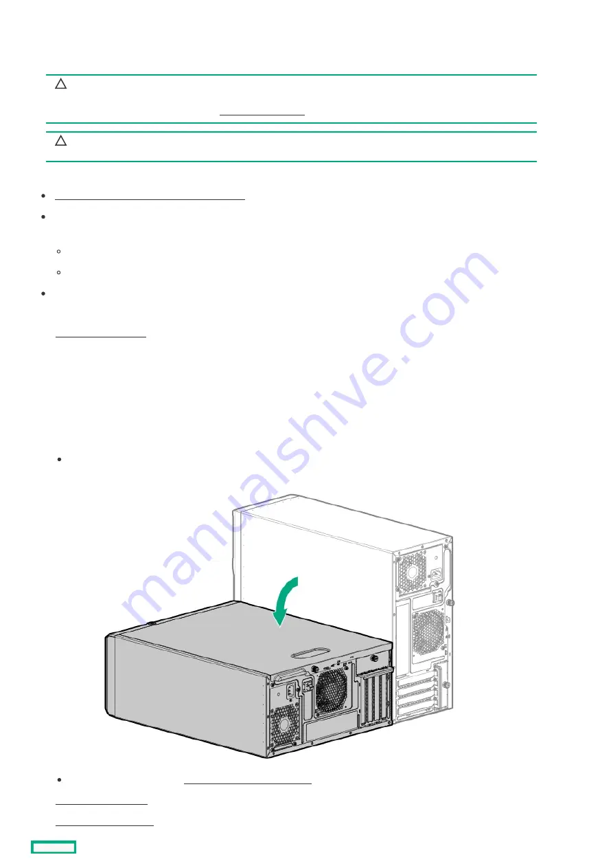
4. Do one of the following:
If the server is in tower mode, place the server on a flat, level surface with the access panel facing up.
If the server is in rack mode, remove the server from the rack .
Installing a USB RDX docking station
106
Summary of Contents for ProLiant ML30 Gen10 Plus
Page 17: ...DIMM slot location The arrow points to the front of the server DIMM slot location 17 ...
Page 40: ...Remove the access panel 40 ...
Page 42: ...Remove the air baffle 42 ...
Page 45: ...Remove a media drive 45 ...
Page 53: ...11 Power up the server Install the server into the rack 53 ...
Page 66: ...doors Rack warnings and cautions 66 ...
Page 76: ...6 Install the server into the rack Install the rack rails and server tray 76 ...
Page 140: ...Installing a DIMM 140 ...
Page 163: ...The installation is complete Installing the M 2 SATA SSD enablement option 163 ...
Page 180: ...Energy pack cabling Energy pack cabling 180 ...
Page 186: ...RDX backup system cabling 186 ...
Page 188: ...Gold SATA connector of the SATA power Y cable Color Description Optical drive cabling 188 ...
Page 190: ...Fan cabling PCI fan cabling System fan cabling Heatsink fan cabling Fan cabling 190 ...
Page 191: ...PCI fan cabling PCI fan cabling 191 ...
Page 192: ...System fan cabling System fan cabling 192 ...
Page 193: ...Heatsink fan cabling Heatsink fan cabling 193 ...
Page 204: ...Troubleshooting NMI functionality Troubleshooting resources Troubleshooting 204 ...
Page 216: ...Ukraine RoHS material content declaration Ukraine RoHS material content declaration 216 ...