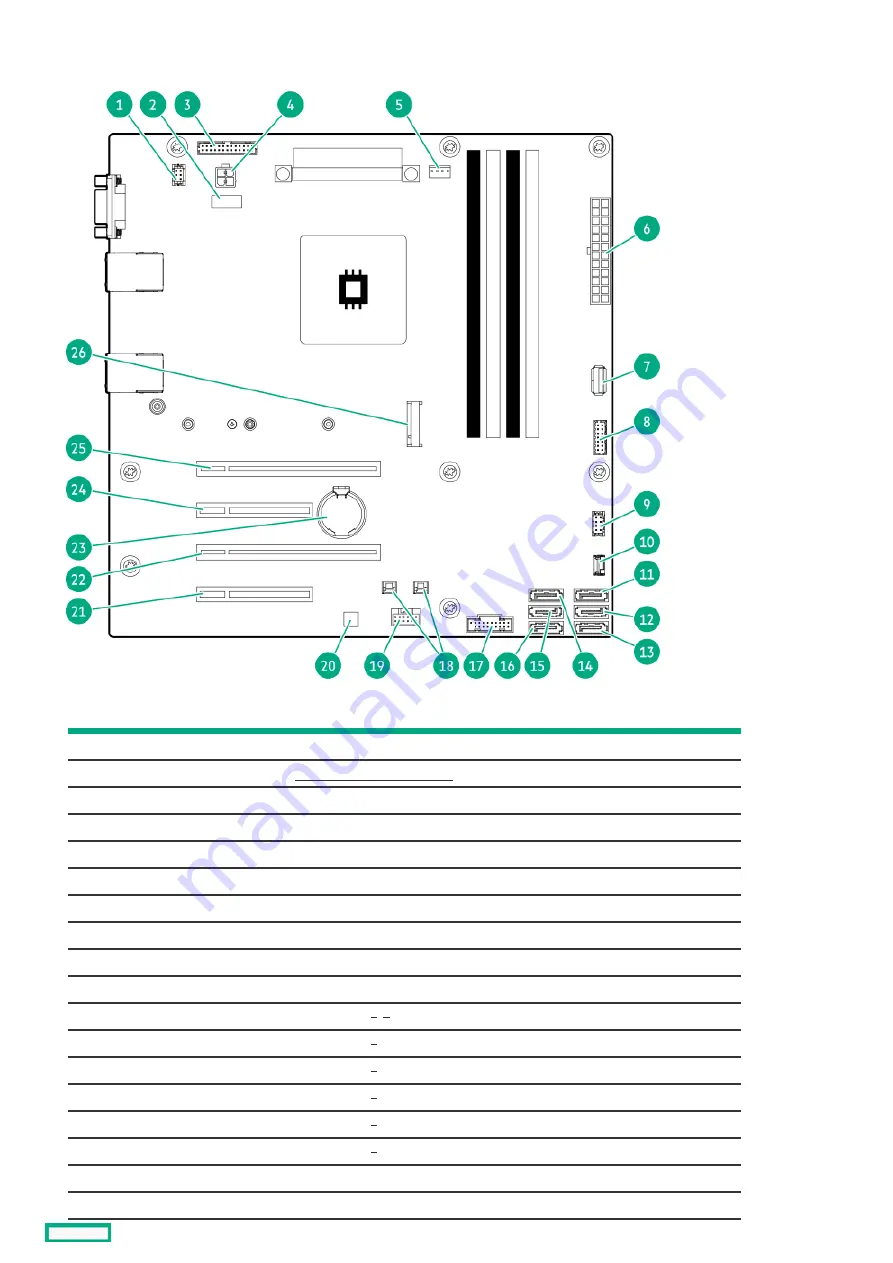
System board components
System board components
Item
Item
Description
Description
1
Fan connector 2 (system fan)
2
3
Flexible Slot power supply sideband connector
4
4-pin power supply connector
5
Fan connector 3 (heatsink fan)
6
24-pin power supply connector
7
Internal USB 3.2 Gen1 port
8
Front I/O connector
9
Fan connector 1 (PCI fan)
10
Drive backplane sideband connector
11
SATA port 5
12
SATA port 6
13
SATA port 1
14
SATA port 2
15
SATA port 3
16
SATA port 4
17
Front USB connector
18
Storage controller backup power connectors
System board components
14
Summary of Contents for ProLiant ML30 Gen10 Plus
Page 17: ...DIMM slot location The arrow points to the front of the server DIMM slot location 17 ...
Page 40: ...Remove the access panel 40 ...
Page 42: ...Remove the air baffle 42 ...
Page 45: ...Remove a media drive 45 ...
Page 53: ...11 Power up the server Install the server into the rack 53 ...
Page 66: ...doors Rack warnings and cautions 66 ...
Page 76: ...6 Install the server into the rack Install the rack rails and server tray 76 ...
Page 140: ...Installing a DIMM 140 ...
Page 163: ...The installation is complete Installing the M 2 SATA SSD enablement option 163 ...
Page 180: ...Energy pack cabling Energy pack cabling 180 ...
Page 186: ...RDX backup system cabling 186 ...
Page 188: ...Gold SATA connector of the SATA power Y cable Color Description Optical drive cabling 188 ...
Page 190: ...Fan cabling PCI fan cabling System fan cabling Heatsink fan cabling Fan cabling 190 ...
Page 191: ...PCI fan cabling PCI fan cabling 191 ...
Page 192: ...System fan cabling System fan cabling 192 ...
Page 193: ...Heatsink fan cabling Heatsink fan cabling 193 ...
Page 204: ...Troubleshooting NMI functionality Troubleshooting resources Troubleshooting 204 ...
Page 216: ...Ukraine RoHS material content declaration Ukraine RoHS material content declaration 216 ...


