


Removal and replacement procedures 28
Symbols on equipment
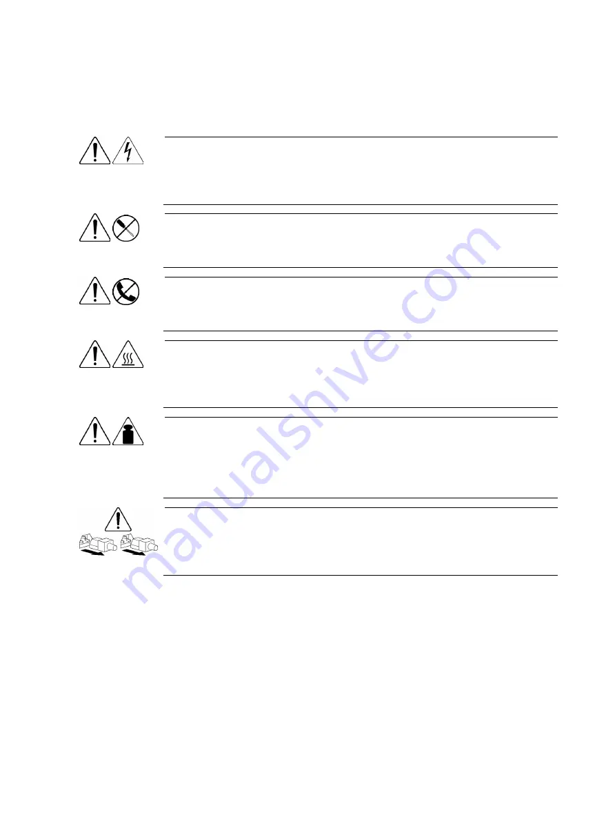
The following symbols may be placed on equipment to indicate the presence of potentially hazardous
conditions:
This symbol indicates the presence of hazardous energy circuits or electric shock
hazards. Refer all servicing to qualified personnel.
To reduce the risk of injury from electric shock hazards, do not open this enclosure.
Refer all maintenance, upgrades, and servicing to qualified personnel.
This symbol indicates the presence of electric shock hazards. The area contains no
user or field serviceable parts. Do not open for any reason.
To reduce the risk of injury from electric shock hazards, do not open this enclosure.
This symbol on an RJ-45 receptacle indicates a network interface connection.
To reduce the risk of electric shock, fire, or damage to the equipment, do not plug
telephone or telecommunications connectors into this receptacle.
This symbol indicates the presence of a hot surface or a hot component. If this surface
is touched, the potential for injury exists.
To reduce the risk of injury from a hot component, allow the surface to cool before
touching.
99.8 kg
220 lb
This symbol indicates that the component exceeds the recommended weight for one
individual to handle safely.
To reduce the risk of personal injury or damage to the equipment, observe local
occupational health and safety requirements and guidelines for manual material
handling.
These symbols, on power supplies or systems, indicate that the equipment is supplied
by multiple sources of power.
To reduce the risk of injury from electric shock, remove all power cords to completely
disconnect power from the system.
Summary of Contents for ProLiant MicroServer
Page 12: ...Customer self repair 12 ...
Page 13: ...Customer self repair 13 ...
Page 14: ...Customer self repair 14 ...
Page 15: ...Customer self repair 15 ...
Page 16: ...Illustrated parts catalog 16 Illustrated parts catalog Mechanical components ...
Page 20: ...Illustrated parts catalog 20 ...
Page 21: ...Illustrated parts catalog 21 System components ...
Page 38: ...Removal and replacement procedures 38 6 Perform the post installation procedure ...
Page 50: ...Removal and replacement procedures 50 5 Perform the post installation procedure ...
Page 66: ...Diagnostic tools 66 5 Click Browse to select folder and then click Next 6 Click Next ...
Page 67: ...Diagnostic tools 67 7 Click Install 8 Click Finish ...
Page 70: ...Diagnostic tools 70 13 Click options Enable or Disable to change Write cache and NCQ status ...


