2.
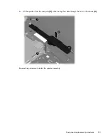
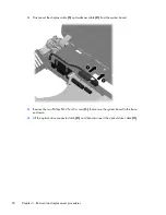
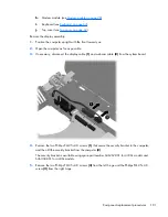
Disconnect the display cable
(1)
and webcam cable
(2)
from the system board.
3.
Remove the two Phillips PM2.5×4.0 screws
(1)
that secure the system board to the base
enclosure.
4.
Lift the optical drive connector latch
(2)
, and then disconnect the optical drive cable
(3)
.
92
Chapter 4 Removal and replacement procedures
Summary of Contents for ProBook 4430s
Page 1: ...HP ProBook 4430s Notebook PC HP ProBook 4330s Notebook PC Maintenance and Service Guide ...
Page 4: ...iv Safety warning notice ...
Page 8: ...viii ...
Page 29: ...Computer major components Computer major components 21 ...
Page 83: ...Cable routing path top Cable routing path bottom Component replacement procedures 75 ...
Page 150: ......

