background image

3.

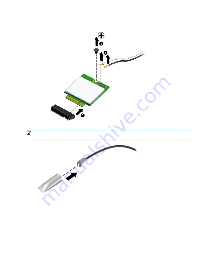
Remove the WLAN module by pulling the module away from the slot at an angle (3).

NOTE:

If the WLAN antennas are not connected to the terminals on the WLAN module, the protective 

sleeves must be installed on the antenna connectors, as shown in the following illustration.

Reverse this procedure to install the WLAN module.

44

Chapter 6   Removal and replacement procedures for Authorized Service Provider parts

Summary of Contents for PAVILION Gaming 17-ak000

Page 1: ...HP 17 Laptop PC AMD Models 17 ak000 17 ak099 Maintenance and Service Guide ...

Page 2: ...26106 001 Product notice This guide describes features that are common to most models Some features may not be available on your computer Not all features are available in all editions or versions of Windows Systems may require upgraded and or separately purchased hardware drivers software or BIOS update to take full advantage of Windows functionality Windows 10 is automatically updated which is a...

Page 3: ... another hard surface such as an adjoining optional printer or a soft surface such as pillows or rugs or clothing to block airflow Also do not allow the AC adapter to contact the skin or a soft surface such as pillows or rugs or clothing during operation The device and the AC adapter comply with the user accessible surface temperature limits defined by the International Standard for Safety of Info...

Page 4: ...iv Safety warning notice ...

Page 5: ...omponents 19 Miscellaneous parts 21 Mass storage devices 22 4 Removal and replacement procedures preliminary requirements 25 Tools required 25 Service considerations 25 Plastic parts 25 Cables and connectors 25 Drive handling 26 Grounding guidelines 26 Electrostatic discharge damage 26 Packaging and transporting guidelines 27 Workstation guidelines 27 5 Removal and replacement procedures for Custo...

Page 6: ... 73 Power connector 74 Top cover keyboard 75 7 Using Setup Utility BIOS 77 Starting Setup Utility BIOS 77 Updating Setup Utility BIOS 77 Determining the BIOS version 77 Downloading a BIOS update 78 8 Backing up restoring and recovering 79 Creating recovery media and backups 79 Creating HP Recovery media select products only 79 Using Windows tools 80 Restore and recovery 81 Recovering using HP Reco...

Page 7: ...omputer specifications 87 43 9 cm 17 3 in display specifications 88 Hard drive specifications 88 M 2 solid state drive specifications 89 DVD RW SuperMulti DL Drive specifications 90 11 Power cord set requirements 91 Requirements for all countries 91 Requirements for specific countries and regions 92 12 Recycling 95 Index 97 vii ...

Page 8: ...viii ...

Page 9: ...phics Switchable discrete graphics AMD Radeon M530 R17M M1 70 with 4096 MB of dedicated video memory AMD Radeon M530 R17M M1 70 with 2048 GB of dedicated video memory Dual graphics AMD Radeon 535DX Dual Graphics Support HD Decode DX12 HDMI and PX7 Support Optimus Panel 16 9 Ultra Wide Aspect Ratio 43 9 cm 17 3 in WLED flat flat 4 0 mm eDP HD SVA BrightView 1600 900 typical brightness 220 nits non ...

Page 10: ...28 in thicknesses 7 2 mm 9 5 mm share the same bracket Single HDD configurations 2 TB 5400 rpm 7 2 mm 9 5 mm 1 TB 5400 rpm 7 2 mm 9 5 mm 500 GB 5400 rpm 7 2 mm M 2 SATA 3 solid state drive 256 GB 128 GB M 2 SATA configurations TLC 256 GB 128 GB Hard drive solid state drive configurations 1 TB 5400 rpm 9 5 mm hard drive 128 GB M 2 SATA 3 solid state drive Fixed optical drive Fixed serial SATA 9 0 m...

Page 11: ... Band Wireless AC 3168 802 11 ac 1x1 WiFi BT 4 2 Combo non vPro Intel Dual Band Wireless AC 7265 802 11AC 2x2 WiFi BT 4 2 Combo Adapter non vPro External media card HP Multi Format Digital Media Card Reader Support SD SDHC SDXC Push push insertion removal Internal Card One M 2 slot for WLAN Ports HDMI version 1 4 supporting 1920 1080 60Hz RJ 45 Ethernet includes link and activity lights USB 3 0 2 ...

Page 12: ...arket EM SL Windows 10 Home EM SL Windows 10 Home Plus EM SL Windows 10 Home Value NB EM SL Windows 10 Home Value NB Select Geo EM SL For China Market CPPP Windows 10 Home High End China Language Edition CPPP Windows 10 Home China Language Edition For APJ SEAP Market EM SL SEAP Windows 10 Home EM SL SEAP Windows 10 Home Value Notebook SEAP Windows 10 Home Plus Ubuntu Standard FreeDOS 2 0 Serviceab...

Page 13: ...e share or access information To insert a card 1 Hold the card label side up with connectors facing the computer 2 Insert the card into the memory card reader and then press in on the card until it is firmly seated To remove a card Press in on the card and then remove it from the memory card reader 4 USB 2 0 port Connects a USB device such as a cell phone camera activity tracker or smartwatch and ...

Page 14: ...s up automatically to cool internal components and prevent overheating It is normal for the internal fan to cycle on and off during routine operation 4 RJ 45 network jack status lights Connects a network cable White The network is connected Amber Activity is occurring on the network 5 HDMI port Connects an optional video or audio device such as a high definition television any compatible digital o...

Page 15: ...amera is in use 2 Camera Allows you to video chat record video and record still images 3 Internal microphone Records sound 4 WLAN antennas Send and receive wireless signals to communicate with wireless local area networks WLANs The antennas are not visible from the outside of the computer and antenna location varies For optimal transmission keep the areas immediately around the antennas free from ...

Page 16: ... your finger gestures to move the pointer or activate items on the screen 2 Left TouchPad button Functions like the left button on an external mouse 3 Right TouchPad button Functions like the right button on an external mouse 8 Chapter 2 Getting to know your computer ...

Page 17: ...Lights Component Description 1 Caps lock light On Caps lock is on which switches the key input to all capital letters 2 Mute light On Computer sound is off Off Computer sound is on Keyboard area 9 ...

Page 18: ...o exit Hibernation CAUTION Pressing and holding down the power button results in the loss of unsaved information If the computer has stopped responding and shutdown procedures are ineffective press and hold the power button down for at least 5 seconds to turn off the computer To learn more about your power settings see your power options Type power in the taskbar search box and then select Power s...

Page 19: ...used system functions NOTE On select products the f5 action key turns the keyboard backlight feature off or on 5 num lock key Alternates between the navigational and numeric functions on the integrated numeric keypad 6 Integrated numeric keypad A separate keypad to the right of the alphabet keyboard When num lock is pressed the keypad can be used like an external numeric keypad NOTE If the keypad ...

Page 20: ...isplay to a simultaneous display on both the computer and the monitor Turns the keyboard backlight off or on select products only NOTE To conserve battery power turn off this feature Mutes or restores speaker sound Decreases speaker volume incrementally while you hold down the key Increases speaker volume incrementally while you hold down the key Plays the previous track of an audio CD or the prev...

Page 21: ...Bottom Component Description 1 Speakers Produce sound 2 Battery lock Locks the battery in the battery bay 3 Battery bay Holds the battery 4 Battery release latch Releases the battery Bottom 13 ...

Page 22: ...the serial number and possibly for the product number or the model number Locate these numbers before you contact support Your service label will resemble one of the examples shown below Refer to the illustration that most closely matches the service label on your computer Component 1 HP product name 2 Model number 3 Product number 4 Serial number 5 Warranty period Regulatory label s Provide s reg...

Page 23: ...TE HP continually improves and changes product parts For complete and current information on supported parts for your computer go to http partsurfer hp com select your country or region and then follow the on screen instructions Computer major components 15 ...

Page 24: ...926196 xxx AMD A10 9620P processor and 2 GB of dedicated video memory 926193 xxx AMD A9 9420 processor and 2 GB of dedicated video memory 926194 xxx AMD A6 9220 processor and 2 GB of dedicated video memory 926195 xxx For use in models with UMA graphics AMD A12 9720P processor 926188 xxx AMD A10 9620P processor 926189 xxx AMD A9 9420 processor 926190 xxx AMD A6 9220 processor 926191 xxx AMD E2 9000...

Page 25: ...046 14 Memory module PC4 2400 8 GB 862398 855 4 GB 862397 855 2 GB 864271 855 15 RTC battery 926546 001 16 WLAN module Intel Dual Band Wireless AC 7265 802 11 AC 2x2 WiFi BT 4 2 Combo Adapter non vPro 793840 005 Realtek RTL8723DE 802 11 bgn 1x1 WiFi BT 4 2 Combo Adapter 927230 855 Realtek RTL 8188EE 802 11 bgn 1x1 WiFi Adapter 927235 855 Intel Dual Band Wireless AC 3168 802 11 ac 1x1 WiFi BT 4 2 C...

Page 26: ...ncludes front and rear feet Pike silver 926547 001 Silk gold 926548 001 Smoke gray 926549 001 Marine blue 926550 001 Amethyst purple 926551 001 Champagne rose 926552 001 Jet black 926553 001 Snow white 926554 001 Empress red 926555 001 Rose gold 926556 001 Pale mint 926557 001 25 Battery 4 cell 41 Whr 2 8 Ah Li ion 919701 850 3 cell 31 Whr 2 8 Ah Li ion 919700 850 26 DVD RW Double Layer SuperMulti...

Page 27: ... EMI foil 926532 001 4 Raw display panel 16 9 Ultra Wide Aspect Ratio 43 9 cm 17 3 in FHD anti glare non touch 798926 012 FHD Touch On Panel TOP 851048 004 HD Touch On Panel TOP 851049 004 HD BrightView non touch 851051 006 HD anti glare non touch 910136 004 5 Hinge covers Left jet black 926533 001 Right jet black 926534 001 Left snow white 926535 001 Display assembly subcomponents 19 ...

Page 28: ... displays 926520 001 Non touch displays 926519 001 8 Antennas Dual 926424 001 Single 926425 001 9 Display enclosure For use in non touch models Pike silver 926482 001 Silk gold 926483 001 Smoke gray 926484 001 Marine blue 926485 001 Amethyst purple 926486 001 Pale mint 926487 001 Champagne rose 926488 001 Jet black 926489 001 Snow white 926490 001 Empress red 926491 001 Rose gold 926492 001 For us...

Page 29: ...ck 1 0 m for use in For use in Australia 920688 011 For use in Denmark 920688 007 For use in Europe 920688 005 For use in North America 920688 001 For use in Switzerland 920688 009 For use in the United Kingdom 920688 006 Rubber Kit includes front and rear feet Pike silver 926547 001 Silk gold 926548 001 Smoke gray 926549 001 Marine blue 926550 001 Amethyst purple 926551 001 Champagne rose 926552 ...

Page 30: ...ge devices Item Component Spare part number 1 DVD RW Double Layer SuperMulti Drive 920417 010 2 Optical drive bezel Pike silver 926505 001 Silk gold 926506 001 Smoke gray 926507 001 Marine blue 926508 001 Amethyst purple 926509 001 Pale mint 926510 001 22 Chapter 3 Illustrated parts catalog ...

Page 31: ...al drive bracket 926526 001 4 Hard drive does not include bracket 2 TB 5400 rpm 2 5 inch 912487 855 1 TB 5400 rpm 2 5 inch 676423 855 500 GB 5400 rpm 2 5 inch 683839 855 5 Hard drive holder 905974 001 6 Solid state drive holder 858260 001 7 Solid state drive board 856614 001 8 Solid state drive 256 GB 865902 015 128 GB 827560 046 Mass storage devices 23 ...

Page 32: ...24 Chapter 3 Illustrated parts catalog ...

Page 33: ... and reassembly can damage plastic parts Use care when handling the plastic parts Apply pressure only at the points designated in the maintenance instructions Cables and connectors CAUTION When servicing the computer be sure that cables are placed in their proper locations during the reassembly process Improper cable placement can damage the computer Cables must be handled with extreme care to avo...

Page 34: ... Electronic components are sensitive to electrostatic discharge ESD Circuitry design and structure determine the degree of sensitivity Networks built into many integrated circuits provide some protection but in many cases ESD contains enough power to alter device parameters or melt silicon junctions A discharge of static electricity from a finger or other conductor can destroy static sensitive dev...

Page 35: ...ly Store reusable ESD sensitive parts from assemblies in protective packaging or non conductive foam Use transporters and conveyors made of antistatic belts and roller bushings Be sure that mechanized equipment used for moving materials is wired to ground and that proper materials are selected to avoid static charging When grounding is not possible use an ionizer to dissipate electric charges Work...

Page 36: ...operator and ground To be effective the conductive must be worn in contact with the skin The following grounding equipment is recommended to prevent electrostatic damage Antistatic tape Antistatic smocks aprons and sleeve protectors Conductive bins and other assembly or soldering aids Nonconductive foam Conductive tabletop workstations with ground cords of one megohm resistance Static dissipative ...

Page 37: ...and current information on supported parts for your computer go to http partsurfer hp com select your country or region and then follow the on screen instructions Component replacement procedures NOTE Please read and follow the procedures described here to access and replace Customer Self Repair parts successfully NOTE Details about your computer including model serial number product key and lengt...

Page 38: ...evices connected to the computer 3 Disconnect the power from the computer by first unplugging the power cord from the AC outlet and then unplugging the AC adapter from the computer To remove the battery 1 Position the computer upside down on a flat surface 2 Slide the battery lock latch 1 to unlock the battery and then slide the battery release latch 2 to release the battery NOTE The battery relea...

Page 39: ... removing the optical drive follow these steps 1 Shut down the computer If you are unsure whether the computer is off or in Hibernation turn the computer on and then shut it down through the operating system 2 Disconnect all external devices connected to the computer 3 Disconnect the power from the computer by first unplugging the power cord from the AC outlet and then unplugging the AC adapter fr...

Page 40: ...ssary to remove the optical drive bezel insert a paper clip into the release hole 1 to disengage the bezel Press the tab 2 to release the bezel from the drive Rotate the side of the bezel 3 and the remove it 4 32 Chapter 5 Removal and replacement procedures for Customer Self Repair parts ...

Page 41: ...t on the rear of the optical drive remove the Phillips PM2 0 2 5 screw 1 that secures the bracket to the drive and then remove the bracket 2 Reverse this procedure to reassemble and install the optical drive Component replacement procedures 33 ...

Page 42: ...34 Chapter 5 Removal and replacement procedures for Customer Self Repair parts ...

Page 43: ...placed or loosened when servicing Authorized Service Provider only parts Make special note of each screw size and location during removal and replacement Display subcomponents bezel webcam panel This section describes removing display subcomponents that do not require that you remove the entire display assembly from the computer You can remove the display bezel webcam microphone module and display...

Page 44: ...mputer 4 Remove the battery see Battery on page 30 To remove the display bezel webcam microphone module and raw display panel 1 Position the computer upright with the front toward you and then open it 2 Flex the inside of the top edge 1 left 2 and right sides 3 and the inside of the bottom edge 4 of the display bezel until the bezel disengages from the display enclosure 3 Remove the display bezel ...

Page 45: ...play panel to the enclosure b Rotate the display panel onto the keyboard 1 to gain access to the display cable connection on the back of the panel c On the back of the display panel release the adhesive strip that secures the display panel cable to the display panel 2 and then disconnect the cable 3 Component replacement procedures 37 ...

Page 46: ...y panel from the computer Reverse this procedure to reassemble and install the display bezel webcam microphone module and display panel 38 Chapter 6 Removal and replacement procedures for Authorized Service Provider parts ...

Page 47: ...uter is off or in Hibernation turn the computer on and then shut it down through the operating system 2 Disconnect all external devices connected to the computer 3 Disconnect the power from the computer by first unplugging the power cord from the AC outlet and then unplugging the AC adapter from the computer 4 Remove the battery see Battery on page 30 5 Remove the optical drive see Optical drive o...

Page 48: ... of the computer and pry to separate the bottom cover from the computer 1 Work your way around prying to disengage the bottom cover from the computer 2 and then remove the cover 3 Reverse this procedure to install the bottom cover 40 Chapter 6 Removal and replacement procedures for Authorized Service Provider parts ...

Page 49: ...turn the computer on and then shut it down through the operating system 2 Disconnect all external devices connected to the computer 3 Disconnect the power from the computer by first unplugging the power cord from the AC outlet and then unplugging the AC adapter from the computer 4 Remove the battery see Battery on page 30 5 Remove the optical drive see Optical drive on page 31 6 Remove the bottom ...

Page 50: ...ter 3 To disassemble the hard drive pull the sides of the cover up and away from the hard drive 1 and then remove the cover from the hard drive 2 Reverse this procedure to reassemble and install the hard drive 42 Chapter 6 Removal and replacement procedures for Authorized Service Provider parts ...

Page 51: ...these steps 1 Shut down the computer If you are unsure whether the computer is off or in Hibernation turn the computer on and then shut it down through the operating system 2 Disconnect all external devices connected to the computer 3 Disconnect the power from the computer by first unplugging the power cord from the AC outlet and then unplugging the AC adapter from the computer 4 Remove the batter...

Page 52: ...ennas are not connected to the terminals on the WLAN module the protective sleeves must be installed on the antenna connectors as shown in the following illustration Reverse this procedure to install the WLAN module 44 Chapter 6 Removal and replacement procedures for Authorized Service Provider parts ...

Page 53: ...e computer 3 Disconnect the power from the computer by first unplugging the power cord from the AC outlet and then unplugging the AC adapter from the computer 4 Remove the battery see Battery on page 30 5 Remove the optical drive see Optical drive on page 31 6 Remove the bottom cover see Bottom cover on page 39 To remove the RTC battery Using a thin tool or screwdriver disengage the battery from t...

Page 54: ...ter by first unplugging the power cord from the AC outlet and then unplugging the AC adapter from the computer 4 Remove the battery see Battery on page 30 5 Remove the optical drive see Optical drive on page 31 6 Remove the bottom cover see Bottom cover on page 39 To remove a memory module 1 Spread the retaining tabs 1 on each side of the memory module slot to release the memory module The memory ...

Page 55: ...from the computer by unplugging the power cord from the computer 3 Remove the battery see Battery on page 30 4 Remove the optical drive see Optical drive on page 31 5 Remove the bottom cover see Bottom cover on page 39 Remove the solid state drive 1 Remove the Phillips PM2 0 2 0 screw 1 that secures the drive to the system board 2 Remove the drive 2 by pulling it away from the connector NOTE Solid...

Page 56: ...ng the AC adapter from the computer 4 Remove the battery see Battery on page 30 5 Remove the optical drive see Optical drive on page 31 6 Remove the bottom cover see Bottom cover on page 39 7 Remove the solid state drive see Solid state drive on page 47 To remove the solid state drive holder and board 1 Remove the Phillips PM2 0 4 5 screw 1 that secures the solid state drive holder to the computer...

Page 57: ...4 Lift the board out of the holder 2 Reverse this procedure to install the solid state drive holder and board Component replacement procedures 49 ...

Page 58: ...power cord from the AC outlet and then unplugging the AC adapter from the computer 4 Remove the battery see Battery on page 30 5 Remove the optical drive see Optical drive on page 31 6 Remove the bottom cover see Bottom cover on page 39 To remove the optical drive connector 1 Disconnect the optical drive connector cable from the system board 1 2 Remove the Phillips PM2 0 4 0 screw 2 that secures t...

Page 59: ...he computer by first unplugging the power cord from the AC outlet and then unplugging the AC adapter from the computer 4 Remove the battery see Battery on page 30 5 Remove the optical drive see Optical drive on page 31 6 Remove the bottom cover see Bottom cover on page 39 To remove the TouchPad click board 1 Disconnect the TouchPad cable from the TouchPad board 1 and the system board cable from th...

Page 60: ...puter by first unplugging the power cord from the AC outlet and then unplugging the AC adapter from the computer 4 Remove the battery see Battery on page 30 5 Remove the optical drive see Optical drive on page 31 6 Remove the bottom cover see Bottom cover on page 39 To remove the USB board 1 Disconnect the cable from the USB board 1 2 Remove the Phillips PM2 0 4 0 screw 2 that secures the USB boar...

Page 61: ...irst unplugging the power cord from the AC outlet and then unplugging the AC adapter from the computer 4 Remove the battery see Battery on page 30 5 Remove the optical drive see Optical drive on page 31 6 Remove the bottom cover see Bottom cover on page 39 To remove the speakers 1 Disconnect the speaker cable from the system board 1 2 Remove the cable from the routing path 2 3 Lift the speakers ou...

Page 62: ... unplugging the power cord from the AC outlet and then unplugging the AC adapter from the computer 4 Remove the battery see Battery on page 30 5 Remove the optical drive see Optical drive on page 31 6 Remove the bottom cover see Bottom cover on page 39 To remove the fan 1 Disconnect the fan cable from the system board 1 2 Remove the Phillips PM2 0 4 0 screw 2 that secures the fan to the computer 3...

Page 63: ...exist These conditions are affected by high external temperatures system power consumption power management battery conservation configurations battery fast charging and software requirements Exhaust air is displaced through the ventilation grill located on the left side of the computer Before removing the heat sink assembly follow these steps 1 Shut down the computer If you are unsure whether the...

Page 64: ...s screws 1 that secure the heat sink to the system board b Remove the heat sink 2 from the system board 3 If you have a model with UMA graphics and no fan a In the order indicated on the heat sink loosen the four Phillips screws 1 that secure the heat sink to the system board 56 Chapter 6 Removal and replacement procedures for Authorized Service Provider parts ...

Page 65: ...ponents each time the heat sink is removed Replacement thermal material is included with the heat sink processor and system board spare part kits The following illustrations show the replacement thermal material locations Discrete graphics Thermal paste is used on the heat sink 1 3 and associated system board components 2 4 Component replacement procedures 57 ...

Page 66: ...em board component 2 UMA graphics on models without fan Thermal paste is used on the heat sink 1 and associated system board component 2 Reverse this procedure to reassemble and install the heat sink assembly 58 Chapter 6 Removal and replacement procedures for Authorized Service Provider parts ...

Page 67: ...xxx Before removing the system board follow these steps 1 Shut down the computer If you are unsure whether the computer is off or in Hibernation turn the computer on and then shut it down through the operating system 2 Disconnect all external devices connected to the computer 3 Disconnect the power from the computer by first unplugging the power cord from the AC outlet and then unplugging the AC a...

Page 68: ...ker cable 5 TouchPad cable 6 Touchpad board cable 7 USB board cable 8 Optical drive connector cable 9 Keyboard cable 2 Remove the seven Phillips PM2 0 3 0 screws 1 that secure the system board to the computer 3 Remove the Phillips broadhead PM2 0 2 0 screw 2 that secures the system board to the computer 60 Chapter 6 Removal and replacement procedures for Authorized Service Provider parts ...

Page 69: ...4 Lift the system board out of the computer 3 Reverse this procedure to install the system board Component replacement procedures 61 ...

Page 70: ...els Pike silver 926482 001 Silk gold 926483 001 Smoke gray 926484 001 Marine blue 926485 001 Amethyst purple 926486 001 Pale mint 926487 001 Champagne rose 926488 001 Jet black 926489 001 Snow white 926490 001 Empress red 926491 001 Rose gold 926492 001 Display enclosure for use in non touch models Pike silver 933291 001 Silk gold 933292 001 Smoke gray 933293 001 Marine blue 933294 001 Amethyst pu...

Page 71: ... 1 Shut down the computer If you are unsure whether the computer is off or in Hibernation turn the computer on and then shut it down through the operating system 2 Disconnect all external devices connected to the computer 3 Disconnect the power from the computer by first unplugging the power cord from the AC outlet and then unplugging the AC adapter from the computer 4 Remove the battery see Batte...

Page 72: ...stem board 4 Remove the two Phillips PM2 5 5 0 screws 1 that secure each hinge to the computer 5 Remove the two Phillips broadhead PM2 0 2 0 screws 2 that secure each hinge to the computer 64 Chapter 6 Removal and replacement procedures for Authorized Service Provider parts ...

Page 73: ...8 Separate the display assembly from the computer 2 If it is necessary to replace any of the display assembly subcomponents 1 Flex the inside of the top edge 1 left 2 and right sides 3 and the inside of the bottom edge 4 of the display bezel until the bezel disengages from the display enclosure Component replacement procedures 65 ...

Page 74: ...he display assembly with the top edge toward you b Lift to disengage the adhesive that secures the webcam microphone module to the display 1 c Disconnect the cable 2 from the module 4 To remove the display panel a Remove the four Phillips PM2 0 3 0 screws that secure the display panel to the enclosure 66 Chapter 6 Removal and replacement procedures for Authorized Service Provider parts ...

Page 75: ... Rotate the display panel onto the keyboard 1 to gain access to the display cable connection on the back of the panel c On the back of the display panel release the adhesive strip that secures the display panel cable to the display panel 2 and then disconnect the cable 3 Component replacement procedures 67 ...

Page 76: ...lay a Remove the two Phillips PM2 0 2 0 screws 1 that secure the touch control board to the top of the display assembly b Lift the board away from the display 2 enough to access the cables underneath c Rotate the board upside down to access the connectors underneath 1 d Disconnect the two cables from the board 2 3 68 Chapter 6 Removal and replacement procedures for Authorized Service Provider part...

Page 77: ...rd the right and the left hinge cover toward the left 2 to remove them from the display c For installation note the routing of the display cable through the left hinge cover 3 and display cable through the right hinge cover 4 7 To remove the display hinges a Remove the Phillips PM2 0 3 0 screw 1 from the top of each hinge and three Phillips PM2 5 4 0 screws 2 from the bottom of each hinge Componen...

Page 78: ...nnas of the display enclosure 1 release the wireless antenna cables from the clips 2 built into the side of the display enclosure and then remove the antennas and cables NOTE Number of antennas and transceivers may vary 70 Chapter 6 Removal and replacement procedures for Authorized Service Provider parts ...

Page 79: ...nd hardware are transferred to the new enclosure Reverse this procedure to reassemble and install the display assembly When reassembling and reinstalling the display assembly use the following images to determine how to correct route the cables in the display In the following image note the location to route the antenna cables 1 and display webcam cable routing bracket 2 In the following image not...

Page 80: ...72 Chapter 6 Removal and replacement procedures for Authorized Service Provider parts ...

Page 81: ...power cord from the AC outlet and then unplugging the AC adapter from the computer 4 Remove the battery see Battery on page 30 5 Remove the optical drive see Optical drive on page 31 6 Remove the bottom cover see Bottom cover on page 39 7 Remove the fan heat sink see Heat sink assembly on page 55 8 Remove the display see Display assembly on page 62 To remove the power button board 1 Disconnect the...

Page 82: ...the power cord from the AC outlet and then unplugging the AC adapter from the computer 4 Remove the battery see Battery on page 30 5 Remove the optical drive see Optical drive on page 31 6 Remove the bottom cover see Bottom cover on page 39 7 Remove the fan heat sink see Heat sink assembly on page 55 8 Remove the display see Display assembly on page 62 To remove the power connector cable Pull the ...

Page 83: ... country or region Spare part number For use in country or region Spare part number For use in country or region Spare part number Belgium A41 Hungary 211 Saudi Arabia 171 Bulgaria 261 Israel BB1 Slovenia BA1 Canada DB1 Italy 061 South Korea AD1 Czech Republic and Slovakia FL1 The Netherlands B31 Spain 071 Denmark Finland and Norway DH1 Portugal 131 Switzerland BG1 France 051 Romania 271 United Ki...

Page 84: ...76 Chapter 6 Removal and replacement procedures for Authorized Service Provider parts ...

Page 85: ...e on the HP website Most BIOS updates on the HP website are packaged in compressed files called SoftPaqs Some download packages contain a file named Readme txt which contains information regarding installing and troubleshooting the file Determining the BIOS version To decide whether you need to update Setup Utility BIOS first determine the BIOS version on your computer To reveal the BIOS version i...

Page 86: ...y the most recent BIOS update and compare it to the BIOS version currently installed on your computer If the update is more recent than your BIOS version make a note of the date name or other identifier You may need this information to locate the update later after it has been downloaded to your hard drive b Follow the on screen instructions to download your selection to the hard drive Make a note...

Page 87: ...the HP Recovery partition on the computer The backup can be used to reinstall the original operating system in cases where the hard drive is corrupted or has been replaced For information on creating recovery media see Creating HP Recovery media select products only on page 79 For information on the recovery options that are available using the recovery media see Using Windows tools on page 80 Use...

Page 88: ...arately to create recovery discs If you use an external optical drive it must be connected directly to a USB port on the computer the drive cannot be connected to a USB port on an external device such as a USB hub If you cannot create DVD media yourself you can obtain recovery discs for your computer from HP See the Worldwide Telephone Numbers booklet included with the computer You can also find c...

Page 89: ...o remove the Recovery partition to reclaim hard drive space HP Recovery Manager offers the Remove Recovery Partition option For more information see Removing the HP Recovery partition select products only on page 84 Recovering using HP Recovery Manager HP Recovery Manager software allows you to recover the computer to its original factory state by using the HP Recovery media that you either create...

Page 90: ...rking To start HP Recovery Manager from the HP Recovery partition IMPORTANT For a tablet with a detachable keyboard connect the tablet to the keyboard base before beginning these steps select products only 1 Type recovery in the taskbar search box select Recovery Manager and then select HP Recovery Environment or For computers or tablets with keyboards attached press f11 while the computer boots o...

Page 91: ...ard base before beginning these steps 1 Insert the HP Recovery media 2 Access the system Startup menu For computers or tablets with keyboards attached Turn on or restart the computer or tablet quickly press esc and then press f9 for boot options For tablets without keyboards Turn on or restart the tablet and then quickly hold down the volume up button then select f9 or Turn on or restart the table...

Page 92: ...overy partition So before you remove the Recovery partition create HP Recovery media see Creating HP Recovery media select products only on page 79 NOTE The Remove Recovery Partition option is only available on products that support this function Follow these steps to remove the HP Recovery partition 1 Type recovery in the taskbar search box and then select HP Recovery Manager 2 Select Remove Reco...

Page 93: ...lowing order a Connected USB drive NOTE To download the HP PC Hardware Diagnostics UEFI tool to a USB drive see Downloading HP PC Hardware Diagnostics UEFI to a USB device on page 85 b Hard drive c BIOS 3 When the diagnostic tool opens select the type of diagnostic test you want to run and then follow the on screen instructions NOTE If you need to stop a diagnostic test press esc Downloading HP PC...

Page 94: ...ides a BIOS crisis recovery tool through the HP PC Hardware Diagnostics 3 in 1 USB key This tool can be used by HP authorized service providers to recover systems that have failed due to a corrupted BIOS For more information about using the 3 in 1 USB key for BIOS crisis recovery go to http www hp com go techcenter pcdiags Additional information is included in the web based training offered by HP ...

Page 95: ... 18 5 V dc 3 5 A or 19 5 V dc 3 33 A 65 W Temperature Operating 5 C to 35 C 41 F to 95 F Nonoperating 20 C to 60 C 4 F to 140 F Relative humidity noncondensing Operating 10 to 90 Nonoperating 5 to 95 Maximum altitude unpressurized Operating 15 m to 3 048 m 50 ft to 10 000 ft Nonoperating 15 m to 12 192 m 50 ft to 40 000 ft NOTE Applicable product safety standards specify thermal limits for plastic...

Page 96: ...5 0 g 115 0 g 92 0 g Interface type SATA SATA SATA Transfer rate Synchronous maximum 300 MB sec 300 MB sec 300 MB sec Security ATA security ATA security ATA security Seek times typical read including setting Single track 1 4 ms 1 4 ms 3 ms Average read write 10 ms 10 ms 13 ms Maximum 12 ms 12 ms 24 ms Logical blocks 3 877 842 922 1 938 921 461 1 048 576 000 Disk rotational speed 5400 rpm 5400 rpm ...

Page 97: ...Up to 280 MB s Up to 67K IOPs Up to 515 MB s Up to 88K IOPs Ready time Maximum to not busy 1 0 s 1 0 s 1 0 s Access times Logical 0 1 ms 0 1 0 1 Total logical sectors 250 069 680 500 118 192 1 000 215 216 Operating temperature Operating Non operating 0 to 70 C 32 F to 158 F 40 to 95 C 40 F to 203 F 0 to 70 C 32 F to 158 F 55 to 90 C 67 F to 194 F 0 to 70 C 32 F to 158 F 40 to 85 C 40 F to 185 F 1 ...

Page 98: ...n Disc diameter Standard disc 12 cm 4 72 in Mini disc 8 cm 3 15 in Disc thickness 1 2 mm 0 047 in Track pitch 0 74 µm Access time CD DVD Random 175 ms 230 ms Full stroke 285 ms 335 ms Audio output level Line out 0 7 Vrms Cache buffer 2 MB Data transfer rate 24X CD ROM 3 600 KB sec 8X DVD ROM 10 800 KB sec 24X CD R 3 600 KB sec 16X CD RW 2 400 KB sec 8X DVD R 10 800 KB sec 4X DVD RW 5 400 KB sec 8X...

Page 99: ...ng requirements are applicable to all countries and regions The length of the power cord set must be at least 1 5 m 5 0 ft and no more than 2 0 m 6 5 ft All power cord sets must be approved by an acceptable accredited agency responsible for evaluation in the country or region where the power cord set will be used The power cord sets must have a minimum current capacity of 10 A and a nominal voltag...

Page 100: ...orea KTL 5 Sweden SEMKO 1 Switzerland SEV 1 Taiwan BSMI 6 Thailand TISI 1 The United Kingdom ASTA 1 The United States UL 2 1 The flexible cord must be Type HO5VV F 3 conductor 0 75mm2 conductor size Power cord set fittings appliance coupler and wall plug must bear the certification mark of the agency responsible for evaluation in the country or region where it will be used 2 The flexible cord must...

Page 101: ...wall plug must bear the CCC certification mark 5 The flexible cord must be Type H05VV F 3X0 75mm2 conductor size KTL logo and individual approval number must be on each element Corset approval number and logo must be printed on a flag label 6 The flexible cord must be Type HVCTF 3X1 25mm2 conductor size Power cord set fittings appliance coupler cable and wall plug must bear the BSMI certification ...

Page 102: ...94 Chapter 11 Power cord set requirements ...

Page 103: ...he battery in general household waste Follow the local laws and regulations in your area for battery disposal HP encourages customers to recycle used electronic hardware HP original print cartridges and rechargeable batteries For more information about recycling programs see the HP Web site at http www hp com recycle 95 ...

Page 104: ...96 Chapter 12 Recycling ...

Page 105: ...moving 35 62 spare part numbers 16 display assembly subcomponents illustrated 19 removing 35 62 display bezel illustrated 19 removing 36 65 display cable illustrated 20 removing 71 display cable frame guide illustrated 16 display enclosure illustrated 20 removing 71 display panel illustrated 19 62 product description 1 removing 37 66 display specifications 88 drive light 5 DVD RW SuperMulti DL Dri...

Page 106: ...ing system 4 optical drive illustrated 18 22 precautions 26 product description 2 removing 31 specifications 90 optical drive cable illustrated 17 optical drive connector removing 50 spare part number 50 optical drive eject button identifying 6 optical drive rear bracket removing 32 33 optical drive identifying 5 original system recovery 81 P packaging guidelines 27 plastic parts service considera...

Page 107: ...llustrated 17 removing 53 specifications computer 87 display 88 DVD RW SuperMulti DL Drive 90 hard drive 88 M 2 solid state drive 89 optical drive 90 supported discs recovery 80 system board removing 59 spare part number 16 59 system recovery 81 system restore point creating 80 system restore point creating 79 T tools required 25 top cover illustrated 16 top cover keyboard 75 touch control board i...

Page 108: ...100 Index ...

Reviews: