background image

3-14

Troubleshooting and Diagnostics

HP OmniBook 6000

Diagnostic Tools

This section describes the following diagnostic tools you can use for troubleshooting and repairing the
OmniBook:


OmniBook DiagTools program (below).


Power-on self-test (page 3-21).


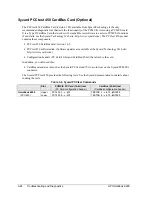
Sycard PCCtest 450 PC Card (page 3-24).


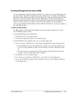
Desktop Management Interface (page 3-25).


BIOS Setup utility (page 3-27).

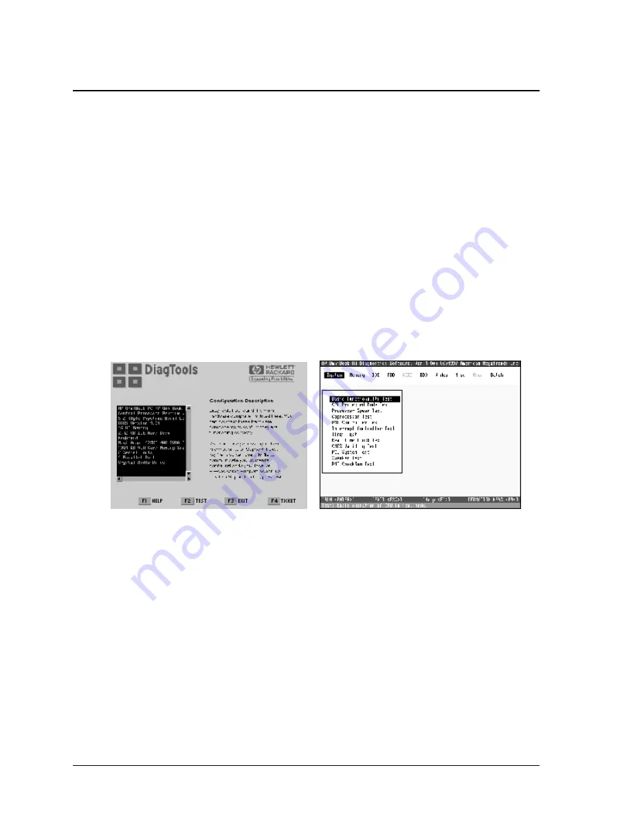
OmniBook DiagTools

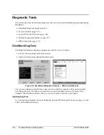
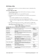
The DiagTools hardware diagnostic program provides two levels of testing:


User-level testing using a basic hardware test.


Advanced testing using individual hardware tests.


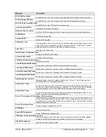
Figure 3-2. OmniBook Diagnostic Screens — Basic and Advanced

The tests are designed to run after the system reboots, so that the computer will be in a predictable
state during the tests. The tests are non-destructive, and are intended to preserve the state of the
computer. The OmniBook reboots when you exit the program so drivers can be loaded.

Updating DiagTools

You can download the latest version of DiagTools from the HP Notebook Web site (see page vi), then
follow the included instructions.

Summary of Contents for OmniBook 6000

Page 1: ... HP OmniBook 6000 Service Manual ...

Page 2: ...mission of Hewlett Packard Company except as allowed under the copyright laws The programs that control this product are copyrighted and all rights are reserved Reproduction adaptation or translation of those programs without prior written permission of Hewlett Packard Co is also prohibited Portions of the programs that control this product may also be copyrighted by Microsoft Corporation SystemSo...

Page 3: ... Only 2 15 Removing the Heatsink with Fan HP Authorized Service Providers Only 2 17 Removing the CPU Module HP Authorized Service Providers Only 2 18 Removing the Top Case HP Authorized Service Providers Only 2 20 Removing the Motherboard or Bottom Case HP Authorized Service Providers Only 2 22 Replacing the Motherboard 2 24 Replacing the Bottom Case 2 27 Repairing the BIOS IC HP Authorized Servic...

Page 4: ...ing the Power Button Panel 2 11 Figure 2 10 Removing the Display 2 14 Figure 2 11 Removing the Keyboard 2 15 Figure 2 12 Unplugging the Keyboard Cables 2 16 Figure 2 13 Removing the Heatsink 2 17 Figure 2 14 Removing the CPU Module 2 19 Figure 2 15 Removing the Top Case 2 21 Figure 2 16 Removing the Motherboard 2 23 Figure 2 17 Replacing Motherboard Components 2 25 Figure 2 18 Installing Docking D...

Page 5: ...umbers 2 6 Table 2 5 Hard Disk Drive Replacement Part Numbers 2 7 Table 2 6 Mini PCI Card Replacement Part Numbers 2 9 Table 2 7 Replacing Small Parts User Replaceable 2 12 Table 2 8 CPU Motherboard Component Compatibility 2 18 Table 2 9 Removing OmniBook Components 2 29 Table 3 1 Scope of Diagnostic Tools 3 4 Table 3 2 Troubleshooting Suggestions 3 5 Table 3 3 OmniBook Diagnostic Error Codes 3 17...

Page 6: ...b Site http www hp com notebooks http www europe hp com notebooks European mirror No usage restriction HP Partnership Web http partner americas hp com Restricted to Authorized Resellers only HP Asia Pacific Channel Support Centre for DPSP Partners http www hp com au Restricted to DPSP Partners only America Online Keyword HP Call 800 827 6364 for membership within the US CompuServe GO HP Call 800 5...

Page 7: ...one F2081x Pentium III 600 500 MHz 14 1 XGA 6 GB CD ROM FDD 64 MB Modem LAN F2082x Pentium III 600 500 MHz 14 1 XGA 6 GB CD ROM FDD 64 MB None F2083x Pentium III 650 500 MHz 14 1 XGA 10 GB CD ROM FDD 128 MB Modem LAN F2084x Pentium III 650 500 MHz 14 1 XGA 10 GB CD ROM FDD 128 MB None F2087x Pentium III 700 600 MHz 14 1 XGA 12 GB DVD FDD 128 MB Modem LAN F2088x Pentium III 700 600 MHz 14 1 XGA 12 ...

Page 8: ...P graphics interface 4 or 8 MB video RAM with 32 or 64 bit graphics interface and 64 bit graphics controller 3D and OpenGL graphics support Up to 16M colors XGA Zoomed Video enabled AGP graphics interface 4 MB video RAM with 32 bit graphics interface and 64 bit graphics controller 3D and OpenGL graphics support Up to 16M colors XGA Zoomed Video enabled Operating System Windows 95 Windows 98 or Win...

Page 9: ...stick pointing device 5 Click buttons and scroll button 6 Touch pad pointing device 7 Click buttons 8 Main status lights left to right power state hard disk activity charging status for main battery and charging status for secondary battery 9 Module eject latch 10 System off switch 11 Audio off button and audio off light 12 Infrared port below the volume control 13 Volume control 14 Audio jacks le...

Page 10: ... disk drive secondary battery or other plug in module 26 Mini PCI cover no user parts inside 27 SDRAM cover Figure 1 3 OmniBook Rear View 28 Universal serial bus port USB 29 Parallel port LPT1 Use this port for a parallel printer or other parallel device or to connect the floppy disk drive externally 30 Docking port 31 PS 2 keyboard or PS 2 mouse port supports Y adapter 32 Serial port COM1 Use thi...

Page 11: ... Saves significant power Turns off the display and other components Maintains current session in SDRAM Restarts quickly Restores network connections Press blue sleep button or click Start Suspend Windows 95 or Start Shutdown Standby Windows 98 and 2000 or allow timeout Press the blue sleep button to display your current session Instant On Hibernate mode Saves maximum power Saves current session to...

Page 12: ...as a fault Off The ac adapter is not connected Secondary battery status Green The ac adapter is connected and the battery is fully charged Amber The ac adapter is connected and the battery is charging Red The battery has a fault Off The ac adapter is not connected a secondary battery is not installed or the battery is not charging The keyboard status lights located above the keyboard indicate the ...

Page 13: ...econd key then release both keys Table 1 6 Fn Hot Keys Hot Key Effect Fn F1 Decreases the display brightness Fn F2 Increases the display brightness Fn F5 Toggles among the built in display an external display and simultaneous display on both Fn F7 Mutes the computer s speakers Fn F8 Toggles the built in keypad on and off Does not affect an external keyboard If Num Lock is on then the numeric funct...

Page 14: ...e power button for 4 seconds until the display shuts down then press the blue sleep button to restart or if this fails Insert a straightened paper clip into the system off switch on the right side of the computer then press the blue sleep button to restart Figure 1 4 Resetting the Computer Note To boot from a CD ROM or DVD drive in the module bay insert a bootable CD such as the Recovery CD into t...

Page 15: ...ntium III models ATI Mobility M1 graphics accelerator with 8 MB display RAM 2x AGP graphics capability Power Rechargeable lithium ion battery with LED charge level gauge 11 1 or 14 8 Vdc Battery life one battery up to 4 hours typical with 8 cell Li Ion 14 8 V battery varies with model and usage Fast battery recharge 80 in 1 5 hour 100 in 2 hours Low battery warning Suspend resume capability Univer...

Page 16: ... V 42 MNP2 4 Fax Group 3 fax Class 1 V 17 V 27ter V 29 V 21 Input Output Universal serial bus USB 9 pin 115 200 bps serial 16550 UART 25 pin bi directional ECP EPP parallel 15 pin VGA video out with DDC support Resolution up to 1600 1200 64K or 16M colors Refresh rate up to 60 to 100 Hz depending on resolution Dual display PS 2 keyboard mouse 4 Mbps IrDA compliant infrared port Expandability One T...

Page 17: ...erating temperature 5 to 35 C 41 to 95 F Operating humidity 20 to 90 percent RH 5 to 35 C Operating altitude up to 3000 m 10 000 ft Storage temperature 20 to 50 C 4 to 122 F Major ICs CPU Intel Mobile Pentium III or Celeron processor South Bridge PIIX4M Display controller ATI Mobility M or M1 Audio controller ESS Maestro 3E and ESS ES1921 CardBus controller TI PCI 1420 Keyboard embedded controller...

Page 18: ...on secondary battery F2019A Lithium ion primary battery 8120 6312 8120 6313 8120 6314 8120 6316 8120 6317 8120 8367 8120 8373 8120 8452 8120 8699 Replacement power cord Australia Replacement power cord U S Canada Taiwan Replacement power cord Europe Replacement power cord Japan Replacement power cord India South Africa Replacement power cord Argentina Replacement power cord People s Rep of China R...

Page 19: ...Book s replaceable electronic modules In addition the table on page 1 14 lists the roles that the replaceable modules play in each of the OmniBook s functional subsystems Figure 1 5 Replaceable Module Diagram Motherboard PCA Heatsink fan CPU module Volume PCA Plug In Module or Battery Main Battery PCMCIA Socket PCMCIA Cards Hard Disk Drive Mini PCI Card Mini PCI Panel Top Case speakers touch pad c...

Page 20: ...ive Motherboard Floppy disk module I O controller floppy connector Floppy disk mechanism Keyboard Motherboard Power supply PCA Keyboard Keyboard BIOS Keyboard controller Key switches Pointer Motherboard Power supply PCA Keyboard Top case Keyboard BIOS pointing stick controller PS 2 output Keyboard controller Pointing stick sensor Touch pad sensor click buttons controller PS 2 output Audio Motherbo...

Page 21: ...ve hard disk page 2 7 Feet rubber page 2 12 Heatsink with fan page 2 17 Keyboard page 2 15 Panel sound IR page 2 29 Panel mini PCI page 2 29 Panel power button page 2 11 Panel vent page 2 29 PCA display interface page 2 29 PCA power supply page 2 29 PCA motherboard page 2 22 PCA volume page 2 29 Plug in module page 2 5 SDRAM module page 2 6 Socket PCMCIA page 2 29 Tray hard disk drive page 2 7 Cau...

Page 22: ...c adapter secondary battery Plug in module hard disk drive Only if removing top case motherboard or bottom case Power button panel Keyboard Heatsink with fan Display assembly Top case Motherboard or bottom case If removing display assembly or hinge covers only CPU module CMOS battery Hinge covers PCMCIA socket Display interface PCA Power supply PCA Volume PCA Mini PCI panel Vent panel Sound IR pan...

Page 23: ...river preferably magnetized Small flat blade screwdriver IC PLCC removal tool similar to OK Industries EX 5 Table 2 3 Recommended Screw Torques Screw Thread Size Torque cm kgf Torque in lbf M2 1 3 1 8 1 1 1 5 M2 5 2 11 mm long 3 0 3 5 2 6 3 0 M2 5 12 19 mm long 2 5 3 0 2 2 2 6 M3 3 0 3 5 2 6 3 0 ...

Page 24: ...one Removal Procedure Slide the battery s release latch then lift the battery out of its compartment Figure 2 2 Removing the Battery Reassembly Notes Insert the front rounded end of the battery into the battery compartment on the bottom of the computer and lower the back end in until it clicks into place ...

Page 25: ... In Module User Replaceable Required Equipment None Removal Procedure 1 Press the button on the module release latch and slide the latch toward the front of the computer Figure 2 3 Removing a Module 2 Grasp the module and pull it out Figure 2 4 Removing a Module ...

Page 26: ...AM module only by its edges and provide proper grounding or you might damage the board by electrostatic discharge Required Equipment Small Phillips screwdriver Removal Procedure 1 Unplug the ac adapter if present and remove the battery Remove the secondary battery if one is installed 2 Turn the unit bottom side up loosen the screw holding the SDRAM cover the cover retains the screw and remove the ...

Page 27: ...mall Phillips screwdriver Removal Procedure 1 Unplug the ac adapter if present and remove the battery Remove the secondary battery if one is installed 2 Turn the unit bottom side up and remove both hard drive screws 3 Raise the cover on the end of the drive so that its retainer tab is free of the computer casing then gently pull the hard drive out of the computer Figure 2 6 Removing the Hard Disk ...

Page 28: ...stall a new hard drive always create a Hibernate partition on the drive before loading any software 1 Plug in the ac adapter 2 Insert the Recovery CD in the CD ROM drive 3 Shut down and restart the computer When you see the HP logo press ESC twice 4 Select the CD or DVD drive as the boot device 5 When the Recovery CD dialog box appears follow the displayed instructions If prompted accept the recom...

Page 29: ...rovide proper grounding or you might damage the board by electrostatic discharge Required Equipment Small Phillips screwdriver Removal Procedure 1 Unplug the ac adapter if present and remove the battery Remove the secondary battery if one is installed 2 Loosen the screw holding the mini PCI cover the cover retains the screw and remove the cover 3 Release the latches at the sides of the board so th...

Page 30: ...val and Replacement HP OmniBook 6000 Reassembly Notes Gently press the mini PCI card into the connector at about a 30 angle until it is fully inserted Then press down on both sides until the latches snap closed ...

Page 31: ...ttery Remove the secondary battery if one is installed 2 Carefully insert the screwdriver blade under the power button panel along the edge shown below and gently pry up the center of the cover 3 Insert a thumb or finger under the center of the panel and lift the panel out Figure 2 9 Removing the Power Button Panel Reassembly Notes Insert the left end of the panel into the top case and press the p...

Page 32: ...loosen the screw in the mini PCI cover the cover retains the screw and remove the cover Cover SDRAM On the bottom of the computer loosen the screw in the SDRAM module cover the cover retains the screw and remove the cover Covers screw on display bezel Insert a small flat blade screwdriver under the cover and pry it loose To replace firmly press the adhesive side of the cover into the recess Covers...

Page 33: ... installed 2 Remove the power button panel page 2 11 3 From the back of the computer remove the two screws near the PS 2 keyboard mouse port and the two near the ac adapter jack 4 From the bottom of the computer remove the two screws from the rear corners 5 Open the display Remove the screw from the display s ground wire and disconnect the main cable 6 Remove the screws from the center hinge cover...

Page 34: ...t Make sure the DIP switches on the display interface PCA match the settings shown on the label on the display cable or you risk damaging the display If you change the DIP switches you must also reprogram the EEPROM for the new display see page 2 26 If the EEPROM is not programmed correctly the display will not turn on Screws M2 5 6mm 5 Screws M2 5 6mm 2 Screws M2 5 6mm 4 Label with DIP switch set...

Page 35: ...nk until it has cooled It could be hot if the computer was running recently 4 Remove the four retaining screws from the tabs along the back end of the keyboard Figure 2 11 Removing the Keyboard 5 Raise the back end of the keyboard then lift the keyboard out of the computer Be careful not to pull on the cables connecting the keyboard to the computer 6 Lay the keyboard face down on the top case slig...

Page 36: ...tes Lay the keyboard face down on the top case slightly forward of its normal position then reconnect the keyboard and pointing stick flex cables Slip the metal tabs on the bottom of the keyboard into their slots in the top case then lower the keyboard into place Keyboard and pointing stick flex cables ...

Page 37: ...pter if present and remove the battery Remove the secondary battery if one is installed 2 Remove these additional assemblies Power button panel page 2 11 Keyboard page 2 15 3 Disconnect the fan cable through the opening in the heatsink 4 Remove the five retaining screws 5 Lift the heatsink out of the unit Figure 2 13 Removing the Heatsink Screws M2 5 6mm 4 Fan cable Fan cable socket Screw M2 4mm ...

Page 38: ...9101 550 MHz PCA motherboard F2072 60913 F2072 60914 Required Equipment Small Phillips screwdriver Small flat blade screwdriver Removal Procedure 1 Unplug the ac adapter if present and remove the battery Remove the secondary battery if one is installed 2 Remove these additional assemblies Power button panel page 2 11 Keyboard page 2 15 Heatsink page 2 17 3 Turn the lock screw one half turn counter...

Page 39: ...s Whenever you install a new CPU you must make sure the SpeedStep power level DIP switches are set correctly for that CPU These switches are located on the motherboard next to the volume PCA and control the power level to the CPU in the SpeedStep high speed mode The settings to use depend on the Q batch number printed on the upper surface of the CPU The following settings are for batch number Q49 ...

Page 40: ... screws holding the left and right corner covers then remove the covers Hint The right corner cover may come off more easily if you slide the plug in module latch forward 4 Remove the four retaining screws from the bottom case 5 Remove the two retaining screws located just inside the hard disk drive compartment 6 Remove the single screw inside the battery compartment 7 From the top of the computer...

Page 41: ...en reinstalling the right corner cover first insert the tab at the back end of the cover into the case then move the plug in module latch forward and snap the cover over the latch and into place Caution Be careful not to pinch the speaker wires when reinstalling the nearby retaining screws Screws M2 5x6mm 2 PCMCIA doors Screws M2 5x6mm 3 Screws M2 5x4mm 2 Cover right corner Panel sound IR Panel ve...

Page 42: ...therboard You will then store the Service ID in the EEPROM on the new motherboard PCA Do this using the Service Utility disk see page 2 26 1 Unplug the ac adapter if present and remove the battery Remove the secondary battery if one is installed 2 Remove these additional assemblies Plug in module page 2 5 Hard disk drive page 2 7 Power button panel page 2 11 Keyboard page 2 15 Heatsink page 2 17 D...

Page 43: ... 16 Removing the Motherboard Reassembly Notes Insert the audio connectors through their openings in the bottom case then lower the motherboard into place When reinstalling the sound IR panel make sure the volume control is oriented properly pins facing inward Insert the tabs on the end of the panel into the slots in the bottom case When installing the vent panel insert the pin on the back end of t...

Page 44: ...Removal and Replacement HP OmniBook 6000 If you need to install or replace the docking or PCMCIA doors see the figures below Figure 2 17 Installing Docking Doors Figure 2 18 Installing the Lower PCMCIA Door ...

Page 45: ...urn counterclockwise to release the CPU module and remove the CPU module from the motherboard 6 Install the above components from the old motherboard on the new motherboard Figure 2 19 Replacing Motherboard Components 7 Make sure the SpeedStep power level DIP switches on the motherboard are set correctly for the CPU See the note on page 2 19 8 Follow the Reassembly Notes on page 2 23 9 Store the s...

Page 46: ...e following Image for creating a bootable Display Update floppy disk Image for creating a bootable Service Utilities floppy disk Readme file that explains how to create and use the above floppy disks Use the Display Update floppy disk and Service Utilities floppy disk as described in the Readme file to update the following data in the EEPROM on the motherboard LCD operating information Computer s ...

Page 47: ...d templates on a PC connected to a laser printer The latest version includes fields for warranty period and manufacturing location 1 Open a new document based on the serial label template 2 Enter the information from the old serial label and print the new label on plain white paper The new label does not have barcodes 3 Carefully cut out the new serial label just inside the border and place it int...

Page 48: ...rrect BIOS Crisis Recovery floppy for the OmniBook model you are repairing The program does not verify the OmniBook model so you could install the wrong BIOS image 1 Insert the BIOS Crisis Recovery floppy in the floppy drive 2 If the computer does not boot from the BIOS Crisis Recovery floppy try plugging the boot block jumper into the OmniBook parallel port then go to the next step See the wiring...

Page 49: ...board page 2 15 Heatsink page 2 17 Reassembly Notes After replacing the CMOS battery set the correct time and date using the BIOS Setup utility or Date Time in the Control Panel Case bottom See page 2 22 Case top See page 2 20 Covers hinge left right or center Power button panel page 2 11 Display assembly page 2 13 Caution When removing the center hinge cover be careful not to pull on or damage th...

Page 50: ...ard page 2 15 Heatsink page 2 17 Display assembly page 2 13 Top case page 2 20 On the rear of the computer remove the screw at the far left end nearest the mini PCI panel Panel vent Plug in module page 2 5 Hard disk drive page 2 7 Power button panel page 2 11 Keyboard page 2 15 Heatsink page 2 17 Display assembly page 2 13 Top case page 2 20 Reassembly Notes Insert the pin on the back end of the p...

Page 51: ...directions provided PCA motherboard See page 2 22 PCA volume Plug in module page 2 5 Hard disk drive page 2 7 Power button panel page 2 11 Keyboard page 2 15 Heatsink page 2 17 Display assembly page 2 13 Top case page 2 20 Remove the screw from the board see the figure on page2 25 and carefully lift the board off of the connector underneath Socket PCMCIA Plug in module page 2 5 Hard disk drive pag...

Page 52: ......

Page 53: ... of the OmniBook and identifying faulty modules Troubleshooting information Troubleshooting the problem page 3 3 Verifying the repair page 3 3 Suggestions for troubleshooting page 3 4 Diagnostic tools OmniBook DiagTools diagnostic program page 3 14 Power on self test page 3 21 Sycard PCCtest 450 PC Card page 3 24 Desktop Management Interface page 3 25 BIOS Setup utility page 3 27 ...

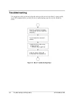
Page 54: ...mends that you follow the basic troubleshooting steps shown in the illustration below Figure 3 1 Basic Troubleshooting Steps Check the customer s description of the problem and any supporting information Try to duplicate the customer s problem Troubleshoot the problem using Diagnostic tools Troubleshooting suggestions Verify the repair by testing the functionality of the complete unit ...

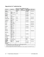
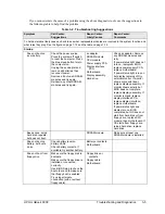
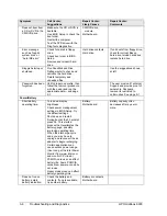
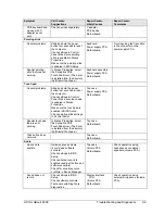
Page 55: ...d PCCtest The table on page 3 4 shows how you can use these tools to isolate the cause of the computer s problem The troubleshooting suggestions on page 3 5 include general suggestions for repairing units with specific failure symptoms Swapping modules that may be defective with others known to be good is generally an ideal way to find the module responsible for the problem A failure symptom is ra...

Page 56: ...nfigures Serial Tests Misc menu Describes Configures Parallel Tests Misc menu Describes Configures LAN Tests User menu Describes Modem Tests User menu Infrared Tests Misc menu Describes Configures PS 2 port Tests KBD Misc menus USB Tests USB menu Describes Docking port Tests using docks PCMCIA Tests Misc menu Tests Describes ac adapter Status Docking products Tests ports and internal bus Status Co...

Page 57: ...light does not turn on reprogram BIOS replace power supply PCA replace motherboard If power status light turns on but display remains off try external monitor If monitor shows successful boot replace display assembly If monitor shows activity but BIOS does not complete replace display assembly If monitor is blank replace display interface PCA replace display interface replace motherboard If power ...

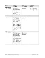
Page 58: ...e removal procedure with the owner and log the appropriate data see page 5 1 The user must call Technical Support and provide proof of ownership Password removal is restricted to certain sites See page 5 1 Power Battery Short battery operating time Turn down display brightness Check power management settings in BIOS Setup Try the default settings Shut down and restart During boot at the F2 prompt ...

Page 59: ... is using power at the moment It therefore depends on the current task and assumes that power will be used at the same rate until the battery runs out So for example if the computer is performing a task requiring a good deal of power such as reading from a CD or DVD the value will probably show too little time remaining Display Dark display no light Adjust display brightness Press Fn F5 several ti...

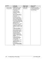
Page 60: ...est the hard disk drive with the DiagTools diagnostics Use the Recovery CD to restore original factory software Use the suggestions shown at left Drive capacity is less than normal Check the disk surface by running Scandisk Windows 95 98 or by using the Tools tab in the disk s Properties sheet Windows 2000 Check partitions using FDISK Windows 95 98 or Control Panel Administrative Tools Computer Ma...

Page 61: ... and hold the power button four seconds to reset the computer Check settings in Control Panel Make sure touch pad is enabled in Mouse Properties Make sure the touch pad is enabled in BIOS Setup Check pointing stick settings in Control Panel Top case Power supply PCA Motherboard Special touch pad features not working In Mouse Properties select the Synaptics PS 2 TouchPad driver The driver is instal...

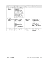
Page 62: ... word length and stop bits match on sending and receiving modems Open the hardware Device Manager If the modem is disabled try to enable it If it has a conflict try disabling another device Use an analog telephone line 2 3 or 4 wires not a PBX or digital line In a hotel ask for a data line Try disabling error correction and data compression Mini PCI card Mini PCI panel Motherboard LAN Network Gene...

Page 63: ...PC card in a docking system insert or remove the card while the system is turned on Download current drivers from the card manufacturer s web site PCMCIA socket Motherboard Using a flashlight look for bent pins inside the PCMCIA socket If both slots have problems replace the motherboard If only one slot has a problem try replacing the PCMCIA socket ac adapter Does not power the OmniBook Try anothe...

Page 64: ...ard disk time out to match the Standby time out Some file browsers respond slowly while processing graphics or waiting for broken network connections to time out Check for overheating see the previous symptom If the computer s hard disk drive frequently runs as indicated by the hard drive light on the front of the computer while the computer appears to be paused or running slowly consider installi...

Page 65: ... sleep button to turn the computer back on Accessories Docking product I O problems Make sure ac power is connected to the dock Make sure computer is fully inserted in dock Check computer s power supply Check settings in BIOS Setup Try using the corresponding port on the computer while undocked Docking product Motherboard Test the corresponding OmniBook ports while undocked The port replicator and...

Page 66: ...provides two levels of testing User level testing using a basic hardware test Advanced testing using individual hardware tests Figure 3 2 OmniBook Diagnostic Screens Basic and Advanced The tests are designed to run after the system reboots so that the computer will be in a predictable state during the tests The tests are non destructive and are intended to preserve the state of the computer The Om...

Page 67: ...izard that runs a set of advanced tests for the failed component Then generate a support ticket 6 If you intend to exit without running the advanced tests press F4 to save system and test information in the Support Ticket log file Then remove the floppy disk if present and press F3 to exit 7 Run the advanced tests Press F2 to open the advanced test screen 8 Select and run the appropriate tests Tes...

Page 68: ... Check the log The log file contains a hardware summary and a list of all test results and errors Run C Dmi Hputils Hpsuppt exe to retrieve the log file to this directory and open it in Notepad Note that the serial and parallel port tests are more thorough if you connect a loop back connector to the port before running the test for that port See the wiring diagrams below 14 1 25 13 6 1 9 5 Figure ...

Page 69: ... all but one SDRAM module and repeat the test Check the CPU module for shorts Replace the CPU module Replace the motherboard 0170h 0172h Replace the motherboard Code Suggestions 0180h Replace the SDRAM module each 01000000h represents 16 MB Replace the motherboard 0181h Enable external cache memory through BIOS Setup Replace the CPU module 0182h Unload HIMEM SYS or any programs using the extended ...

Page 70: ...lled and constructed properly For the external or internal loopback test replace the motherboard 0602h Replace the motherboard Code Suggestions 0603h For the external loopback test make sure the loopback connector is installed and constructed properly For the external or internal loopback test replace the motherboard 0604h 0605h Replace the motherboard 0606h For the external loopback test make sur...

Page 71: ...06h Insert a different PC Card and repeat the test Replace the PCMCIA socket Replace the motherboard 1207h Reset the computer Replace the motherboard Code Suggestions USB Tests 1301h Reprogram the BIOS IC Replace the power supply PCA Replace the motherboard 1302h 1316h Replace the motherboard 9006h See USB Port Test below DVD Tests 1900h 1902h Insert a different DVD in the drive and repeat the tes...

Page 72: ...isk 9605h Run full HDD test For a computer that does not give an F10 prompt at boot no Hibernate partition or that has a non Windows operating system this error may not indicate a failure Otherwise reformat the hard disk If necessary recreate the Hibernate partition then run FDISK to partition the hard disk Code Suggestions 9606h Run the full HDD test Reformat the hard disk If necessary recreate t...

Page 73: ...r fails to boot with a clean boot it requires repair If an error message appears confirm the problem using other diagnostic tools Not all POST messages indicate a hardware software or firmware failure some messages are for information only If the BIOS detects a terminal error condition it halts POST after issuing a terminal error beep code see the following table The beep code indicates the POST r...

Page 74: ...uration used System CMOS has been corrupted or modified incorrectly perhaps by an application program that changes data stored in CMOS The BIOS installed Default Setup Values If you do not want these values enter Setup and enter your own values If the error persists check the system battery Connect the ac adapter for at least 24 hours replace the motherboard 0260 System timer error The timer test ...

Page 75: ...nnnn is the amount of shadow RAM in kilobytes successfully tested nnnn kB System RAM Passed Where nnnn is the amount of system RAM in kilobytes successfully tested Operating system not found Operating system cannot be located on either drive A or drive C Enter Setup and see if fixed disk and drive A are properly identified Parity Check 1 nnnn Parity error found in the system bus BIOS attempts to l...

Page 76: ...us Card version 1 05 PCCtest 450 software disk Software updates are available at the Sycard Technology Web site http www sycard com Configuration headers PC Card 16 bit and CardBus 32 bit that attach to the card In addition you will need this CardBus extender card such as the Sycard PCCextend 70 to avoid wear on the Sycard PCMCIA connector The Sycard PCCtest 450 provides the following tests See th...

Page 77: ...I Package The DMI package is included with the OmniBook but must be properly installed before it can be used Install the package as follows To install the DMI preloaded on the hard disk 1 Start Windows if it is not already running 2 Click Start Programs HP TopTools for Notebooks Setup To install the DMI from the OmniBook Recovery CD or from floppy disks 1 If you do not have a CD ROM drive create i...

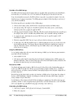
Page 78: ...ing for Remote Application connection requests If the main window of the Remote Agent is hidden then no icon will appear on the screen when it is running Using the DMI Interface For a complete explanation of how to take full advantage of DMI see the following documentation provided with the OmniBook A README TXT file A Windows online help file describing Hewlett Packard s implementation of DMI gro...

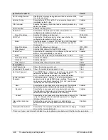
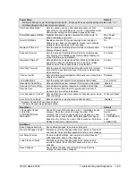
Page 79: ...uced with BIOS version 1 00 Spring 2000 Main Menu Default BIOS Revision Shows the current BIOS version Detected automatically System Time Sets the time using 24 hour format Values set take effect immediately System Date Sets the date using mm dd yy English or dd mm yy format Floppy Drive Sets the floppy drive type Detected and set automatically Internal Hard Disk Sets the hard disk drive type and ...

Page 80: ...Q7 DMA channel Sets the DMA channel for ECP mode DMA3 Security Menu Default User Password is Shows if a user password is set Clear Administrator Password is Shows if an administrator password is set Clear Set User Password Press ENTER to set change or clear the user password The password can have no more than 8 characters 0 9 A Z and cannot include special or accented characters Enter Set Administ...

Page 81: ... Disabled Lid Switch Mode Sets the action that occurs if the computer s lid is closed Turn off LCD Resume On Serial Ring Sets whether the system resumes if it received a ring signal Enabled Resume On Time of Day Sets whether the system resumes at a defined time of day Disabled Resume Time Sets the 24 hour time when the system resumes from if Resume On Time of Day is enabled Auto Suspend on Undock ...

Page 82: ......

Page 83: ...able Parts 4 1 4 Replaceable Parts This chapter contains an exploded view of the OmniBook and the following lists of parts OmniBook replaceable parts page 4 3 Accessory replacement parts page 4 5 Part number reference page 4 6 ...

Page 84: ...4 2 Replaceable Parts HP OmniBook 6000 Figure 4 1 Exploded View ...

Page 85: ...831 F2072 69104 Yes 7 Drive hard disk 12 GB 9 5 mm Hitachi 0950 3733 F1660 69107 Yes 7 Drive hard disk 18 GB 12 7 mm IBM 0950 3712 F1660 69106 Yes 8 Heatsink with fan F2072 60908 9 Keyboard Arabic English F2072 60949 9 Keyboard Belgian F2072 60944 9 Keyboard Czech F2072 60943 9 Keyboard Danish F2072 60941 9 Keyboard French F2072 60936 9 Keyboard French Canadian F2072 60933 9 Keyboard German F2072 ...

Page 86: ...CA power supply F2072 60911 24 PCA volume F2072 60912 SDRAM module 32 MB SODIMM 100 MHz 1818 7950 Yes SDRAM module 64 MB SODIMM 100 MHz 1818 7951 F1660 69103 Yes SDRAM module 128 MB SODIMM 100 MHz 1818 7952 F1660 69104 Yes SDRAM module 256 MB SODIMM 100 MHz 1818 7953 F1654 69101 Yes Set covers service F2072 60924 25 Panel sound IR see above kit 26 Panel vent see above kit 27 Doors PCMCIA with spri...

Page 87: ...10 Yes Drive CD ROM module F2017 60901 Yes Drive CD RW module F2026 60901 F2026 69001 Yes Drive DVD module F2015 60901 Yes Drive floppy disk module F2013 60901 Yes Drive LS 120 module F2022 60901 Yes Drive Zip module F2009 60901 Yes Mini dock F1452 60901 Yes Module weight saving F2072 60922 Yes Monitor stand short F1453 60901 Yes Monitor stand tall F1477 60936 Yes Plug adapter auto air 5182 5131 Y...

Page 88: ... Celeron 5182 5131 Plug adapter auto air Yes 8120 6312 Cord power Australia ABG 2w Yes 8120 6313 Cord power US ABA 2w Yes 8120 6314 Cord power Europe ABB 2w Yes 8120 6316 Cord power Japan ABJ 2w Yes 8120 6317 Cord power S Africa ACQ 2w Yes 8120 8367 Cord power Argentina 2w Yes 8120 8373 Cord power China AB2 2w Yes 8120 8452 Cord power Chile 2w Yes 8120 8699 Cord power UK EPSR for Hong Kong 2w Yes ...

Page 89: ... F2072 60923 Kit OB6000 screws Yes F2072 60924 Set covers service F2072 60925 Set mini PCI panels F2072 60926 Kit OB6000 feet bumpers Yes F2072 60927 Set covers user Yes F2072 60928 Keyboard US English F2072 60929 Keyboard International English F2072 60930 Keyboard Greek F2072 60931 Keyboard Turkish F2072 60932 Keyboard UK English F2072 60933 Keyboard French Canadian F2072 60934 Keyboard German F2...

Page 90: ...072 60965 Recovery CD Italian W95 F2072 60966 Recovery CD Czech W98 F2072 60967 Recovery CD Hungarian W98 F2072 60968 Recovery CD Polish W98 F2072 60969 Recovery CD Russian W98 F2072 60970 Recovery CD Arabic W98 F2072 60971 Recovery CD Traditional Chinese W98 F2072 60972 Recovery CD English W2K F2072 60973 Recovery CD German W2K F2072 60974 Recovery CD Spanish W2K F2072 60975 Recovery CD French W2...

Page 91: ...ctual and current owner This requires a sales receipt showing the unit serial number and owner s name or a written statement from the owner attesting that he or she is the owner of the unit The statement can be a fax copy of the document The fact that the unit is in the hands of an HP representative on behalf of the customer is not evidence of ownership In addition HP will not remove the password ...

Page 92: ...ndows or in some other application or combination of applications you should make the determination under those same applications Self test is not a normal operating condition and is not a sufficient tool for interpreting display quality 2 Use the table below to determine whether the display should be considered for replacement These are the only conditions in this guideline that may call for a re...

Page 93: ...f multiple defective dots within 15 mm Mechanical Imperfections Discoloration Polarizer bubbles dents b Any polarizer bubble discoloration or dent that is visible from at least 36 cm 14 in Definitions of imperfections a Bright or dark dot a subpixel red green or blue dot that is stuck on or off b Polarizer dent or bubble a light spot with a darker border that appears on a lighted display and does ...

Page 94: ...ion HP OmniBook 6000 Service Notes Service notes containing important repair information for the HP OmniBook 6000 will be issued periodically as needed These notes are available online at the Partnership Web site see page vi ...

Page 95: ......
Page 96: ...1 Product Information 2 Removal and Replacement 3 Troubleshooting and Diagnostics 4 Replaceable Parts 5 Reference Information Part Number F2072 90045 Printed in U S A 4 00 ...

Reviews: