HP OmniBook 6000
Removal and Replacement
2-25
Replacing the Motherboard
Installation Procedure
Caution
Replace the motherboard only with one that is compatible with the OmniBook model and CPU
module—see the table on page 2-18.
1.
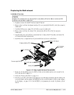
If present, remove the mini-PCI card and mini-PCI panel.
2.
Remove the screw from the display interface PCA, and carefully lift the PCA off of the connector
underneath.
3.
Carefully lift the power supply PCA off of the connector underneath.
4.
Remove the screw from the volume PCA, and carefully lift the PCA off of the connector
underneath.
5.
Turn the lock screw one-half turn counterclockwise to release the CPU module, and remove the
CPU module from the motherboard.
6.
Install the above components from the old motherboard on the new motherboard.
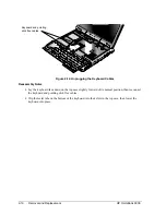
Figure 2-19. Replacing Motherboard Components
7.
Make sure the SpeedStep power level DIP switches on the motherboard are set correctly for the
CPU. See the note on page 2-19.
8.
Follow the “Reassembly Notes” on page 2-23.
9.
Store the service ID, serial number, keyboard layout, and display information electronically in the
new motherboard, and reprogram the EEPROM on the new motherboard with the proper settings
for the display—see page 2-26. If the EEPROM is not programmed correctly, the display will not
turn on.
Power supply PCA
Volume PCA
Screw, M2.5x4mm
CPU module
lock screw
Screw, M2.5x4mm
Display interface PCA
Screws, M2x4mm (2)
Summary of Contents for OmniBook 6000
Page 1: ... HP OmniBook 6000 Service Manual ...
Page 52: ......
Page 82: ......
Page 84: ...4 2 Replaceable Parts HP OmniBook 6000 Figure 4 1 Exploded View ...
Page 95: ......

