HP OmniBook 6000
Removal and Replacement
2-31
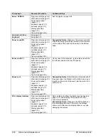
Component
Removal Procedure
Additional Steps
PCA, power supply
Plug-in module (page 2-5).
Hard disk drive (page 2-7).
Power button panel
(page 2-11).
Keyboard (page 2-15).
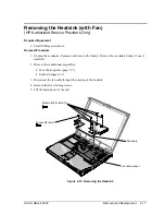
Heatsink (page 2-17).
Display assembly
(page 2-13).
Top case (page 2-20).
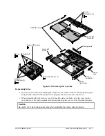
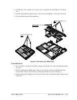
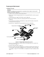
Carefully lift the board off of the connector underneath
(see the figure on page 2-25).
Reassembly Note: The BIOS IC on a new power
supply PCA contains only enough basic programming
to boot the OmniBook. After installing the new PCA,
you must reprogram the BIOS IC, preferably with the
latest BIOS. You can download the latest BIOS from
the HP Notebook Web site (see page vi)—follow the
directions provided.
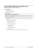
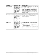
PCA, motherboard
See page 2-22.
PCA, volume
Plug-in module (page 2-5).
Hard disk drive (page 2-7).
Power button panel
(page 2-11).
Keyboard (page 2-15).
Heatsink (page 2-17).
Display assembly
(page 2-13).
Top case (page 2-20).
Remove the screw from the board (see the figure on
page2-25), and carefully lift the board off of the
connector underneath.
Socket, PCMCIA
Plug-in module (page 2-5).
Hard disk drive (page 2-7).
Power button panel
(page 2-11).
Keyboard (page 2-15).
Heatsink (page 2-17).
Display assembly
(page 2-13).
Top case (page 2-20).
1. On the bottom of the computer, loosen the screw
holding the mini-PCI cover (the cover retains the
screw), and remove the cover.
2. Remove both screws (M2x4mm) from inside the
mini-PCI compartment.
3. Remove the two screws attaching the socket to the
motherboard (see the figure on page 2-25).
4. Unplug the PCMCIA socket from the motherboard.
Summary of Contents for OmniBook 6000
Page 1: ... HP OmniBook 6000 Service Manual ...
Page 52: ......
Page 82: ......
Page 84: ...4 2 Replaceable Parts HP OmniBook 6000 Figure 4 1 Exploded View ...
Page 95: ......

