background image

Chapter 2

Installing the Server

Wheel Kit Installation

61

Step 16.

Insert the slot on the caster cover into the front caster. Secure the cover to the server by tightening 
the captive screw on the cover at the rear of the server.

Figure 2-15 Securing Each Caster Cover to the Server

Step 17.

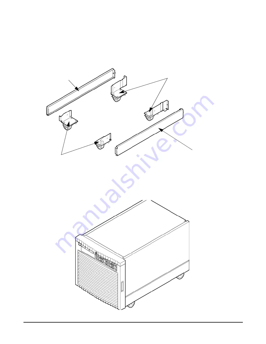
Wheel kit installation is complete when both caster covers are attached to the server, and the front 
bezel and all covers are installed.

Figure 2-16 Completed Server

Caster Cover

Caster Cover

Rear Casters

Front Casters

Summary of Contents for Integrity rx7640

Page 1: ...Installation Guide HP Integrity rx7640 and HP 9000 rp7440 Servers Third Edition Manufacturing Part Number AB312 9001C January 2007 Printed in the U S A Copyright 2007 ...

Page 2: ...ying such products and services Nothing herein should be construed as constituting an additional warranty HP shall not be liable for technical or editorial errors or omissions contained herein Microsoft and Windows are U S registered trademarks of Microsoft Corporation Linux is a U S registered trademark of Linus Torvalds Intel is a trademark or registered trademark of Intel Corporation or its sus...

Page 3: ... and Storage 63 Installing Additional Hard Disk Drives 63 Removable Media Drive Installation 65 PCI X Card Cage Assembly I O Cards 66 Installing an A6869B VGA USB PCI Card in a Server 70 Troubleshooting the A6869B VGA USB PCI Card 72 Cabling and Power Up 73 Checking the Voltage 73 Voltage Check Additional Procedure 77 Connecting AC Input Power 78 Installing The Line Cord Anchor for rack mounted se...

Page 4: ...Contents 4 ...

Page 5: ...Contents 5 ...

Page 6: ...Contents 6 ...

Page 7: ...Contents 7 ...

Page 8: ...Contents 8 ...

Page 9: ... paths for Cell 0 36 Table 1 4 PCI X Paths Cell 1 37 Table 1 5 PCI X Slot Types 38 Table 2 1 Wheel Kit Packing List 55 Table 2 2 Caster Part Numbers 59 Table 2 3 HP Integrity rx7640 PCI X I O Cards 66 Table 2 4 Single Phase Voltage Examples 74 Table 2 5 Factory Integrated Installation Checklist 95 ...

Page 10: ...Tables 10 ...

Page 11: ...he Lifter to the Pallet 53 Figure 2 9 Raising the Server Off the Pallet Cushions 54 Figure 2 10 Component Locations 56 Figure 2 11 Left Foam Block Position 57 Figure 2 12 Right Foam Block Position 58 Figure 2 13 Foam Block Removal 59 Figure 2 14 Attaching a Caster to the Server 60 Figure 2 15 Securing Each Caster Cover to the Server 61 Figure 2 16 Completed Server 61 Figure 2 17 Disk Drive and DVD...

Page 12: ...Figures 12 Figure 2 32 The ls Command Screen 88 Figure 2 33 Example sa Command 89 Figure 2 34 Browser Window 89 Figure 2 35 The du Command Screen 90 Figure 2 36 Console Output Device menu 91 ...

Page 13: ...Figures 13 ...

Page 14: ...Figures 14 ...

Page 15: ...Integrity rx7640 and HP 9000 rp7440 Servers This document does not describe system software or partition configuration in any detail For detailed information concerning those topics refer to the HP System Partitions Guide Administration for nPartitions ...

Page 16: ...16 Book Layout This document contains the following chapters and appendices Chapter 1 Overview Chapter 2 Installing the Server ...

Page 17: ...nting History below identifies the edition dates of this document Updates are made to this publication on an unscheduled as needed basis The updates will consist of a complete replacement document and pertinent on line or CD ROM documentation First Edition March 2006 Second Edition September 2006 Third Edition Minor edits Added information about the rp7440 Server January 2007 ...

Page 18: ...ine and offline diagnostics and event monitoring tools is at the http docs hp com hpux diag Web site This site has documents tutorials FAQs and other reference material Web Site for HP Technical Support http us support2 external hp com HP IT resource center Web site at http us support2 external hp com provides comprehensive support information for IT professionals on a wide variety of topics inclu...

Page 19: ...ed with text that you supply is represented using this font Example Enter the ls l filename command means you must replace filename with your own text Keyboard keys and graphical interface items such as buttons tabs and menu items are represented using this font Examples The Control key the OK button the General tab the Options menu Menu Submenu represents a menu selection you can perform Example ...

Page 20: ...es Your Comments Hewlett Packard welcomes your feedback on this publication Please address your comments to edit presskit rsn hp com and note that you will not receive an immediate reply All comments are appreciated ...

Page 21: ...21 1 HP Integrity rx7640 Server and HP 9000 rp7440 Server Overview The HP Integrity rx7640 and HP 9000 rp7440 servers are members of HP s business critical computing platform family in the mid range product line ...

Page 22: ...roller CC per cell board Turbo fans to cool CPUs and CCs on the cell boards Up to four embedded hard disk drives One half height DVD drive two slimline DVDs or one DAT drive Two front chassis mounted N 1 fans Two rear chassis mounted N 1 fans Six N 1 PCI X card cage fans Two N 1 bulk power supplies N 1 hot swappable system oscillators Sixteen PCI X slots divided into two partitions Each partition ...

Page 23: ...Block Diagram Memory Cell Board 0 CPU CPU CPU CPU CC PDH SBA LBA LBA LBA LBA LBA LBA LBA LBA LBA LBA LBA LBA LBA LBA LBA LBA SBA Backplane System Clocks Bulk Power Supply x2 PCI X x2 Power Reset Memory CC CPU PDH CPU CPU CPU Cell Board 0 CC Link SCSI LAN LBA SCSI LAN SBA Link LAN SCSI Boards PCI X MP SCSI Boards LAN SCSI MP SCSI LBA Disk Backplane Disk Disk Disk Disk DVD PCI SCSI Tape Indicates ho...

Page 24: ...egrity rx7640 Server and HP 9000 rp7440 Server Overview Detailed Server Description 24 Dimensions and Components The following section describes server dimensions and components Figure 1 2 Server Front View With Bezel ...

Page 25: ...es overall package dimension including 2 7 inches protruding in front of the front rack columns Width 44 45 cm 17 5 inches constrained by EIA standard 19 inch racks Height 10U 0 54 cm 43 91 cm 17 287 inches This is the appropriate height for a product that consumes 10U of rack height while allowing adequate clearance between products directly above and below this product Fitting four server units ...

Page 26: ... package This enclosure houses the N 1 fully redundant BPSs Install these power supplies from the front of the server after removing the front bezel Figure 1 4 Right Front View Access the PCI X card section located toward the rear by removing the top cover The PCI card bulkhead connectors are located at the rear top The PCI OLR fan modules are located in front of the PCI X cards These six 9 2 cm f...

Page 27: ...m the rear of the BPSs to the system backplane provides DC power distribution Access the system backplane by removing the left side cover The system backplane hinges from the lower edge and is anchored at the top with two jack screws The SCSI ribbon cable assembly routes from the mass storage area to the backside of the system backplane for connection to the MP SCSI card and to the AB290A LAN SCSI...

Page 28: ... and Controls The front panel located on the front of the server includes the power switch Refer to Figure 1 6 Enclosure Status LEDs The following status LEDs are on the front panel Locate LED blue Power LED tri color Management processor MP status LED tri color Cell 0 1 status tri color LEDs Figure 1 6 Front Panel LEDs and Power Switch ...

Page 29: ...g the other cell board in a configured partition Figure 1 7 Cell Board The server has a 48 V distributed power system and receives the 48 V power from the system backplane board The cell board contains DC to DC converters to generate the required voltage rails The DC to DC converters on the cell board do not provide N 1 redundancy The cell board contains the following major buses Two front side bu...

Page 30: ...ld up to four CPU modules Each CPU module can contain up to two CPU cores on a single socket Modules are populated in increments of one On a cell board the processor modules must be the same family type and clock frequencies Mixing of different processors on a cell board or partition is not supported Refer to Table 1 1 for the load order that must be maintained when adding processor modules to the...

Page 31: ... and DIMMs Address and control signals are fanned out through register ports to the synchronous dynamic random access memory SDRAM on the DIMMs Table 1 1 Cell Board CPU Module Load Order Number of CPU Modules Installed Socket 2 Socket 3 Socket 1 Socket 0 1 Empty slot Empty slot Empty slot CPU installed 2 CPU installed Empty slot Empty slot CPU installed 3 CPU installed Empty slot CPU installed CPU...

Page 32: ...ed by the server are custom designed by HP Each DIMM contains DDR II SDRAM memory that operates at 533 MT s Industry standard DIMM modules do not support the high availability and shared memory features of the server Therefore industry standard DIMM modules are not supported The server supports DIMMs with densities of 1 2 and 4 Gb Table 1 2 on page 33 lists each supported DIMM size the resulting t...

Page 33: ...g system Each nPartition can boot reboot and operate independently of any other nPartitions and hardware within the same server complex The server complex includes all hardware within an nPartition server all cabinets cells I O chassis I O devices and racks management and interconnecting hardware power supplies and fans A server complex can contain one or two nPartitions enabling the hardware to f...

Page 34: ... 1 through the core I O card for cell 1 Figure 1 10 Disk Drive and DVD Drive Location System Backplane The system backplane contains the following components The system clock generation logic The system reset generation logic DC to DC converters Power monitor logic Two local bus adapter LBA chips that create internal PCI buses for communicating with the core I O card Drive 1 1 Path 1 0 0 3 0 6 0 D...

Page 35: ...he high speed data signals are routed from the SBA chips on the PCI X backplane to the two LBA PCI bus controllers on the system backplane Clocks and Reset The system backplane contains reset and clock circuitry that propagates through the whole system The system backplane central clocks drive all major chip set clocks The system central clock circuitry features redundant hot swappable oscillators...

Page 36: ...cell column refers to the cell board installed in the server in cell slot 0 and in cell slot 1 Table 1 3 PCI X paths for Cell 0 Cell PCI X Slot IO Chassis Path 0 1 0 0 0 8 1 0 2 0 0 0 10 1 0 3 0 0 0 12 1 0 4 0 0 0 14 1 0 5 0 0 0 6 1 0 6 0 0 0 4 1 0 7 0 0 0 2 1 0 8 0 0 0 1 1 PCI Slot 8 LBA 1 Cell Controller CC Cell Board PCI Slot 7 LBA 2 PCI Slot 6 LBA 4 PCI Slot 5 LBA 6 PCI Slot 4 LBA 14 PCI Slot ...

Page 37: ...een of the slots have dual ropes connected to the LBA chips The remaining two slots have a single rope connected to each LBA chip Each of the sixteen slots are capable of 66 MHz 33 MHz PCI or 133 MHz 66 MHz PCI X Four slots in PCI X support 266 MHz All sixteen PCI slots are keyed for 3 3 volt connectors accepting both Universal and 3 3 V cards See Table 1 5 for more details The PCI X backplane is ...

Page 38: ...en at the slow speed Maximum MHz Maximum Peak Bandwidth Ropes Supported Cards PCI Mode Supported 0 8 133 533 MB s 001 3 3 V PCI or PCI X Mode 1 7 133 1 06 GB s 002 003 3 3 V PCI or PCI X Mode 1 6 266 2 13 GB s 004 005 3 3 V or 1 5 V PCI X Mode 2 5 266 2 13 GB s 006 007 3 3 V or 1 5 V PCI X Mode 2 4 266 2 13 GB s 014 015 3 3 V or 1 5 V PCI X Mode 2 3 266 2 13 GB s 012 013 3 3 V or 1 5 V PCI X Mode ...

Page 39: ...hat can accommodate either a second LAN SCSI board or any other supported add in PCI X card The LAN SCSI board is hot pluggable Mass Storage Disk Backplane Internal mass storage connections to disks are routed on the mass storage backplane which has connectors and termination logic All hard disks are hot plug but removable media disks are not The servers accommodate one internal half height remova...

Page 40: ...Chapter 1 HP Integrity rx7640 Server and HP 9000 rp7440 Server Overview Detailed Server Description 40 ...

Page 41: ... 2 41 2 Installing the Server Inspect shipping containers when the equipment arrives at the site Check equipment after the packing has been removed This chapter discusses how to inspect and install the server ...

Page 42: ...t arrives at the customer site carefully inspect each carton for signs of shipping damage If the container is damaged document the damage with photographs and contact the transport carrier immediately NOTE The factory provides an installation warranty that is effective from the time the customer receives the shipment until Field Services turns the system over to the customer Upon inspection of a r...

Page 43: ...1 Removing the Polystraps and Cardboard Step 3 Remove the corrugated wrap from the pallet Step 4 Remove the packing materials CAUTION Cut the plastic wrapping material off rather than pull it off Pulling the plastic covering off represents an electrostatic discharge ESD hazard to the hardware Step 5 Remove the four bolts holding down the ramps and remove the ramps ...

Page 44: ...gure 2 2 shows one ramp attached to the pallet on either side of the cabinet with each ramp secured to the pallet using two bolts In an alternate configuration the ramps are secured together on one side of the cabinet with one bolt Figure 2 2 Removing the Shipping Bolts and Plastic Cover ...

Page 45: ...olling the cabinet off the ramp A single server in the cabinet weighs approximately 508 lb It is strongly recommended that two people roll the cabinet off the pallet After unpacking the cabinet examine it for damage that might have been obscured by the shipping container If you discover damage document the damage with photographs and contact the transport carrier immediately If the equipment has a...

Page 46: ...the Server Cabinet 46 Securing the Cabinet When in position secure and stabilize the cabinet using the leveling feet at the corners of the base Figure 2 4 Install the anti tip mechanisms on the bottom front and rear of the rack Figure 2 4 Securing the Cabinet ...

Page 47: ...A 11 Rack Mount System Installation Information is available to help with rack mounting the server This list is intended to guide the HP Installation Specialist to the documentation that has been written by the Rack and Power team The server can be installed in both the 10000 Series Rack and the Rack System E The external Web site is http h18004 www1 hp com products servers platforms rackandpower ...

Page 48: ...n damage to the server Step 1 Follow the instructions on the outside of the service packaging to remove the banding and cardboard top from the server pallet Step 2 Reduce the weight by removing the bulk power supplies and cell boards Place each on an ESD approved surface CAUTION System damage can occur through improper removal and reinstallation of bulk power supplies and cell boards Step 3 Remove...

Page 49: ...he Server Lifting the Server Cabinet Manually 49 Step 5 Insert the 2 protruding tabs on rear flange of handle into the slotted keyways in the server s chassis See Figure 2 5 Figure 2 5 Inserting Rear Handle Tabs into Chassis ...

Page 50: ...ng the Front of Handle to Chassis Step 7 Repeat steps 2 4 to install the other handle on the other side of the server Step 8 After handles are secured server is ready to lift Step 9 Handles are removed in reverse order of steps 2 4 Step 10 After moving the server remove the lift handles from the chassis Step 11 After the server is secured replace the previously removed cell boards and bulk power s...

Page 51: ...n written by RonI and is available on the HP Cybrary http cybrary inet cpqcorp net ARCHIVE PUBS USERS LIFTOFLEX 17000 pdf Complete details on how to assemble the lifter troubleshoot the lifter and maintain the lifter are provided by RonI Use the following procedure to unload the server from the pallet after the lifter is assembled WARNING Use caution when using the lifter To avoid injury because o...

Page 52: ...before proceeding with the rack mount procedure This guide covers these important steps Installing the anti tip stabilizer kit A5540A Installing the ballast kit J1479A Installing the barrel nuts on the front and rear columns Installing the slides Step 2 Follow the instructions on the outside of the server packaging to remove the banding and carton top from the server pallet ...

Page 53: ...Lifting Device 53 Step 3 Insert the lifter forks between the cushions Figure 2 8 Positioning the Lifter to the Pallet Step 4 Carefully roll the lift forward until it is fully positioned against the side of the server Position the lifter forks at these insertion points ...

Page 54: ...allet Cushions Step 6 Carefully roll the lifter and server away from the pallet Do not raise the server any higher than necessary when moving it over to the rack Step 7 Follow the HP J1530C Rack Integration Kit Installation Guide to complete these steps Mounting the server to the slides Installing the cable management arm CMA Installing the interlock device assembly if two servers are in the same ...

Page 55: ...hile cutting the plastic bands around the shipping container These bands are under tension When cut they can spring back and cause serious eye injury Table 2 1 Wheel Kit Packing List Part Number Description Quantity A6753 04013 Wheel Kit consisting of the following components 1 A6753 04002 Side cover 1 A6753 04003 Side cover 1 A6753 04004 Top cover 1 A6753 00007 Caster cover 2 A6753 04001 Right fr...

Page 56: ...ut and remove the polystrap bands securing the HP server to the pallet Step 2 Lift the carton top from the cardboard tray resting on the pallet Step 3 Remove the bezel kit carton and the top cushions from the pallet Figure 2 10Component Locations Step 4 Unfold bottom cardboard tray Top Cushions Cardboard Tray Bezel Kit ...

Page 57: ... Wheel Kit Installation 57 Step 5 Carefully tilt the server and place one of the foam blocks A6093 44002 under the left side of the server Do not remove any other cushions until instructed to do so Figure 2 11Left Foam Block Position ...

Page 58: ...r 2 Installing the Server Wheel Kit Installation 58 Step 6 Carefully tilt the server and place the other foam block provided in the kit under the right side of the server Figure 2 12Right Foam Block Position ...

Page 59: ...side cushions Figure 2 13Foam Block Removal Step 8 Locate and identify the caster assemblies Use the following table to identify the casters NOTE The caster part number is stamped on the caster mounting plate Table 2 2 Caster Part Numbers Caster Part Number Right front A6753 04001 Right rear A6753 04005 Left front A6753 04006 Left rear A6753 04007 ...

Page 60: ...supplied in the plastic pouch Step 11 Remove the foam blocks from the left and right side of the server Step 12 Locate the plywood ramp Step 13 Attach the ramp to the edge of the pallet NOTE There are two pre drilled holes in the ramp Use the two screws taped to the ramp to attach the ramp to the pallet Step 14 Carefully roll the server off the pallet and down the ramp Step 15 Locate the caster co...

Page 61: ...ver by tightening the captive screw on the cover at the rear of the server Figure 2 15 Securing Each Caster Cover to the Server Step 17 Wheel kit installation is complete when both caster covers are attached to the server and the front bezel and all covers are installed Figure 2 16 Completed Server Caster Cover Caster Cover Rear Casters Front Casters ...

Page 62: ...ets The 60A IEC PDU has four 16A circuit breakers and is constructed for International use Each of the four circuit breakers has two IEC 320 C19 outlets providing a total of eight IEC 320 C19 outlets Each PDU is 3U high and is rack mounted in the server cabinet Documentation for installation will accompany the PDU The documentation can also be found at the external Rack Solutions Web site at http ...

Page 63: ...located in the front of the chassis Figure 2 17 The hard disk drives are hot plug drives A list of replacement disk drives for the server is in Appendix A of the HP Service Guide The list contains both removable media disk drives and hard disk drives Figure 2 17 Disk Drive and DVD Drive Location Use the following procedure to install the disk drives Step 1 Be sure the front locking latch is open t...

Page 64: ...isk drive into the chassis a slow firm pressure is needed to properly seat the connector Step 3 Press the front locking latch to secure the disk drive in the chassis Step 4 If the server OS is running spin up the disk by entering one of the following commands diskinfo v dev rdsk cxtxdx ioscan f ...

Page 65: ... filler panel from the server Step 3 Install the left and right media rails and clips to the drive Step 4 Connect the cables to the rear of the drive Step 5 Fold the cables out of the way and slide the drive into the chassis The drive easily slides into the chassis however a slow firm pressure is needed for proper seating The front locking tab will latch to secure the drive in the chassis Step 6 R...

Page 66: ...thernet 1000b SX A4929A Gigabit Ethernet 1000b T A5158A FCMS Tachlite A5230A 10 100b TX RJ45 A5506B 4 port 10 100b TX A5838A 2 port Ultra2 SCSI 2 Port 100b T Combo A6386A Hyperfabric II A6749A 64 port Terminal MUX A6795A 2G FC Tachlite B A6825A Next Gen 1000b T b b A6826A1 2 port 2Gb FC B B A6828A 1 port U160 SCSI B B A6829A 2 port U160 SCSI B B A6847A Next Gen 1000b SX b b A6869B2 Obsidian 2 VGA ...

Page 67: ...B1 QLogic 2 port 4Gb FC card PCI X 266 B B B B AB429A1 1 Port 4Gb FC QLogic AB378A equivalent B B AB465A1 2 port 1000b T 2Gb FC Combo Bb B AB466A1 Emulex 1050DC Fibre Channel B AB467A1 Emulex 1050D Fibre Channel B AB545A 4 Port 1000b T Ethernet b AD167A1 Emulex 4Gb s B B AD168A1 Emulex 4Gb s DC B B AD278A 8 Port Terminal MUX AD279A 64 Port Terminal MUX J3525A 2 port Serial 337972 B21 SA P600 Redst...

Page 68: ... PCI slot then power off the PCI slot using the rad o command This will allow future OLAR operations to succeed on this PCI slot IMPORTANT The installation process varies depending on what method for installing the PCI card is selected PCI I O card installation procedures should be downloaded from the http docs hp com Web site Background information and procedures for adding a new PCI I O card usi...

Page 69: ... or replacement OLAR The attention button is also referred to as the doorbell Step 1 Remove the top cover Step 2 Remove the PCI bulkhead filler panel Step 3 Flip the PCI manual retention latch MRL for the card slot to the open position Refer to Figure 2 19 Step 4 Install the new PCI card in the slot NOTE Apply a slow firm pressure to properly seat the card into the backplane Step 5 Flip the PCI MR...

Page 70: ...ort Guide located on the Web at http docs hp com for details Step 9 Replace the top cover Step 10 Connect all cables to the installed PCI card Installing an A6869B VGA USB PCI Card in a Server The A6869B VGA USB PCI card is a dual function combo card hosting VGA and universal serial bus USB controllers Both of these devices sit behind a PCI PCI bridge The A6869B VGA USB PCI card operates at the co...

Page 71: ... be added or replaced online while Windows remains running For these cards you must shut down Windows on the nPartition before performing the card replacement or addition See the section on Shutting Down nPartitions and Powering off Hardware Components in the appropriate service guide 1 If the A6869B VGA USB PCI card is currently not installed follow proper procedures to shut down the nPartition a...

Page 72: ...ures available for HP Servers at this website including links to download Windows Drivers HP Servers Technical Support http www hp com support itaniumservers Black Screen No text displayed Hardware problem Must have supported power enabled Must have a functional VGA USB PCI card Must have a functional PCI slot Select another slot on same partition backplane Must have the VGA USB PCI card firmly se...

Page 73: ... voltage check refer to the section titled Voltage Check Additional Procedure on page 77 Preface The server requires a minimum of 2 power cords To enable full power redundancy 4 power cords may be used When using 4 power cords dual power sources may be used to provide additional power source protection Power cords are designated and labeled A0 A1 B0 and B1 Cords A0 and B0 should be energized from ...

Page 74: ...and ground In North America verify that this voltage is between 100 120 VAC In Europe and certain parts of Asia Pacific verify that this voltage is 0 zero V AC Table 2 4 provides single phase voltage measurement examples dependent on the geographic region where these measurements are taken Verifying the Safety Ground Single Power Source Use this procedure to measure the voltage level between A0 an...

Page 75: ...e other probe into the ground pin for A1 4 Verify that the measurement is between 0 5 V AC If the measurement is 5 V or greater escalate the situation Do not attempt to plug the power cord into the server cabinet Step 2 Measure the voltage between B0 and B1 as follows 1 Take the AC voltage down to the lowest scale on the volt meter 2 Insert the probe into the ground pin for B0 3 Insert the other p...

Page 76: ...d probes Be sure to replace access cover when finished testing primary power Step 1 Measure the voltage between A0 and A1 as follows 1 Take the AC voltage down to the lowest scale on the volt meter 2 Insert the probe into the ground pin for A0 3 Insert the other probe into the ground pin for A1 4 Verify that the measurement is between 0 5 V AC If the measurement is 5 V or greater escalate the situ...

Page 77: ...sert the other probe into the ground pin for B1 4 Verify that the measurement is between 0 5 V AC If the measurement is 5 V or greater escalate the situation Do not attempt to plug the power cord into the server cabinet Voltage Check Additional Procedure The voltage check ensures that all phases and neutral for international systems are connected correctly to the cabinet and that the AC input volt...

Page 78: ...ck the connector in place WARNING Do not set site AC circuit breakers serving the processor cabinets to ON before verifying that the cabinet has been wired into the site AC power supply correctly Failure to do so may result in injury to personnel or damage to equipment when AC power is applied to the cabinet Step 8 Set the site power circuit breaker to ON Step 9 Set the server power to ON Step 10 ...

Page 79: ...ingle line cord configuration is not allowed The power cord configuration is passed to the operating system using the pwrgrd Power Grid command Each of the five selections in the pwrgrd command matches one of the configurations The appropriate option should be selected for the actual line cord configuration With the correct configuration selected the LEDs should be green when the pwrgrd command is...

Page 80: ...ce between the data and power cables is 3 inches 7 62 cm The power cord has current flowing through it which creates a magnetic field The potential to induce electromagnetic interference in the data cables exists which can cause data corruption NOTE Label the AC power cords during the installation One suggestion is to use tie wraps that have the flag molded into the tie wrap The flag can be labele...

Page 81: ...ese studs To install the line cord anchor 1 Remove and retain the thumb nuts from the studs 2 Install the line cord anchor over the studs Refer to Figure 2 27 Two Cell Line Cord Anchor rp7410 rp7420 rp7440 rx7620 rx7640 3 Tighten the thumb nuts onto the studs 4 Weave the power cables through the line cord anchor Leave enough slack to allow the plugs to be disconnected from the receptacles without ...

Page 82: ...P SCSI board include the following DB9 connector for Local Console 10 100 Base T LAN RJ45 connector for LAN and Web Console access This LAN uses standby power and is active when AC is present and the front panel power switch is off Internal LVD Ultra 320 SCSI channel for connections to internal mass storage Internal SE Ultra SCSI channel for connection to an internal removable media device LAN SCS...

Page 83: ...ng down cell board power Establish communication with the MP by connecting the CE Tool to the local RS 232 port on the MP core I O card Setting CE Tool Parameters After powering on the CE Tool ensure the communications settings are as follows 8 data bits no parity 9600 baud na Receive na Transmit ...

Page 84: ... enabled it provides direct access to the MP and any partition Use the following procedure to connect the CE Tool to the Local RS 232 Port on the MP 1 Connect one end of a null modem cable 9 pin to 9 pin Part Number 5182 4794 to the cable connector labeled CONSOLE 2 Connect the other end of the RS 232 cable to the CE Tool Turning on Housekeeping Power and Logging in to the MP After connecting the ...

Page 85: ...n power is first applied The BPS LEDs will be flashing amber After 30 seconds has elapsed The flashing amber BPS LED for each BPS becomes a flashing green LED Refer to power cord policies to interpret LED indicators 3 Log in to the MP a Enter Admin at the login prompt The login is case sensitive It takes a few moments for the MP prompt to display If it does not be sure the laptop serial device set...

Page 86: ...LAN port information LAN information includes the MP network name the MP IP address the subnet mask and the gatway address This information is provided by the customer To set the MP LAN IP address Step 1 At the MP Main Menu prompt MP enter cm to enter the MP Command NOTE If the Command Menu is not shown enter q to return to the MP Main Menu then enter cm Step 2 From the MP Command Menu prompt MP C...

Page 87: ...or the customer LAN The name can be as many as 64 characters in length and include alphanumeric characters dash _ under bar period or a space HP recommends that the name be a derivative of the complex name For example Acme com_MP Step 8 Enter the LAN parameters for the Subnet mask and Gateway address fields This information must come from the customer When this step is completed the system will in...

Page 88: ...MP configuration must be done from an ASCII console connected to the Local RS232 port NOTE The MP SCSI card has a separate LAN port from the system LAN port It requires a separate LAN drop IP address and networking information from that of the port used by HP UX Before starting this procedure the following information is required IP address for the MP LAN Subnet mask Gateway address Host name this...

Page 89: ...pt to display and set MP remote access Figure 2 33 Example sa Command Step 5 Enter W to modify web access mode Step 6 Enter option 2 to enable web access Step 7 Launch a Web browser on the same subnet using the IP address for the MP LAN port Figure 2 34 Browser Window Zoom In Out Title Bar ...

Page 90: ... boards Step 1 At the MP prompt enter cm This displays the Command Menu The Command Menu enables viewing or modifying the configuration and viewing the utilities controlled by the MP To view a list of the commands available enter he Press Enter to see more than one screen of commands Use the Page Up and Page Down keys to view the previous or next screen of commands To exit the Help Menu enter q St...

Page 91: ... and your hardware you can select one of two possible devices as your system console The possibilities are Management Processor MP Serial Port VGA device Step 2 Select the appropriate console device deselect unused devices a Choose the Boot option maintenance menu choice from the main Boot Manager Menu b Select the Console Output Input or Error devices menu item for the device type you are modifyi...

Page 92: ...output If incorrect console devices are chosen the OS may fail to boot or will boot with output directed to the wrong location Therefore any time new potential console devices are added to the system or anytime NVRAM on the system is cleared console selections should be reviewed to ensure that they are correct Configuring the Server for HP UX Installation Installation of the HP UX operating system...

Page 93: ... for each cabinet The following events occur Power is applied to the server Processor dependent code PDC starts to run on each cell The cell self test executes Hardware initializes for the server Console communication is established Step 2 After the cell has joined the partition or after boot is blocked BIB is displayed at the Virtual Front Panel VFP return to the MP Main Menu by pressing Ctrl B S...

Page 94: ...Consoles Menu MP co Select a partition number Step 5 Return to the Main Menu by pressing Ctrl B Step 6 At the EFI Shell prompt select the file system to boot Generally this is fs0 Shell fs0 Step 7 At the fs0 prompt type HPUX to boot the HP UX operating system fso hpux NOTE If the partition fails to boot or if the server was shipped without Instant Ignition booting from a DVD that contains the oper...

Page 95: ...n be found at http docs hp com en B9073 90134 index html NOTE Ensure that the customer is aware of the Instant Capacity email requirements Refer to http docs hp com for further details Installation Checklist The checklist in Table 2 5 is an installation aid Use it only after you have installed several systems by following the detailed procedures described in the body of this document This checklis...

Page 96: ...ral cabinet if ordered Unpack other equipment Remove and dispose of packaging material Move cabinet s and equipment to computer room Move cabinets into final position Position cabinets next to each other approximately 1 2 inch Adjust leveling feet Install anti tip plates Inspect cables for proper installation Set up CE tool and connect to Remote RS 232 port on MP Apply power to cabinet Housekeepin...

Page 97: ...non factory integrated I O cards if required Select PCI card slot Install PCI card Verify installation Route cables using the cable management arm Install other peripherals if required Perform visual inspection and complete installation Set up network services if required Enable iCOD if available Final inspection of circuit boards Final inspection of cabling Area cleaned and debris and packing mat...

Page 98: ...ng the Server Cabling and Power Up 98 Make entry in Gold Book recommended Customer acceptance and signoff if required Table 2 5 Factory Integrated Installation Checklist Continued Continued Procedure In process Completed ...

Page 99: ...cell 92 HP UX Installation 92 I inspecting for damage 42 installation checklist 95 warranty 42 IP address default 86 L LED Attention 85 Bulk Power Supply 85 management processor 28 remote port 28 SP Active 85 Standby Power Good 85 traffic light 28 login name MP 85 M Management Processor MP 82 mass storage backplane 39 memory 22 MP login name 85 password 85 MP Management Processor logging in 84 pow...

Page 100: ...ng parameters 82 83 server front panel 28 service processor 22 Standby power LED 28 status LEDs 28 system backplane 27 35 38 system configuration verifying 93 T turbocoolers 22 U unpacking inspecting for damage 42 V verifying system configuration 93 voltage check 77 W warranty 42 ...

Page 101: ...Index 101 ...

Reviews: