HP HP EliteBook 1040 G1 Maintenance And Service Manual Download Page 16

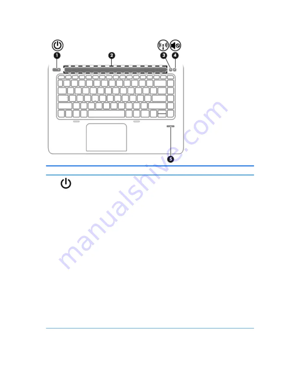
Buttons and fingerprint reader

Component

Description

(1)

Power button

When the computer is off, press the button to turn on the

computer.

When the computer is on, press the button briefly to initiate

Sleep.

When the computer is in the Sleep state, press the button

briefly to exit Sleep.

When the computer is in Hibernation, press the button

briefly to exit Hibernation.

CAUTION:

Pressing and holding down the power button will

result in the loss of unsaved information.

If the computer has stopped responding and Windows®

shutdown procedures are ineffective, press and hold the power

button for at least 5 seconds to turn off the computer.

If the computer has stopped responding and the previous

shutdown procedures are ineffective, press and hold the power

volume mute button for at least 5 seconds to perform a

hardware reset turning off the computer.

To learn more about your power settings in Windows 8, see your

power options. From the Start screen, type 

power

, select 

Power

and sleep settings

, and then select 

Power and sleep

 from the

list of applications.

To learn more about your power settings in Windows 7: Select

Start > Control Panel > System and Security > Power Options

.

To learn more about your power settings in Linux: Select

Computer > Control Center

. In the left pane, click 

System

, and

then click 

Power Management

 in the right pane.

8

Chapter 2   External component identification

Summary of Contents for HP EliteBook 1040 G1

Page 1: ...HP EliteBook Folio 1040 G1 Notebook PC Maintenance and Service Guide ...

Page 2: ...tuting an additional warranty HP shall not be liable for technical or editorial errors or omissions contained herein First Edition December 2013 Document Part Number 738834 001 Product notice This guide describes features that are common to most models Some features may not be available on your computer Not all features are available on all editions of Windows 8 This computer may require upgraded ...

Page 3: ...w another hard surface such as an adjoining optional printer or a soft surface such as pillows or rugs or clothing to block airflow Also do not allow the AC adapter to contact the skin or a soft surface such as pillows or rugs or clothing during operation The device and the AC adapter comply with the user accessible surface temperature limits defined by the International Standard for Safety of Inf...

Page 4: ...iv Safety warning notice ...

Page 5: ...ustrated parts catalog 16 Computer major components 16 Display assembly subcomponents 19 Plastics Kit 20 Mass storage devices 20 Miscellaneous parts 21 Sequential part number listing 22 4 Removal and replacement procedures preliminary requirements 26 Tools required 26 Service considerations 26 Plastic parts 26 Cables and connectors 26 Drive handling 27 Grounding guidelines 27 Electrostatic dischar...

Page 6: ... 67 6 Computer Setup BIOS MultiBoot and HP PC Hardware Diagnostics UEFI in Windows 8 69 Using Computer Setup 69 Starting Computer Setup 69 Navigating and selecting in Computer Setup 69 Restoring factory settings in Computer Setup 70 Updating the BIOS 70 Determining the BIOS version 70 Downloading a BIOS update 71 Using MultiBoot 72 About the boot device order 72 Choosing MultiBoot preferences 72 S...

Page 7: ...lect models only 79 Downloading HP PC Hardware Diagnostics UEFI to a USB device 74 8 Computer Setup BIOS and Advanced System Diagnostics in Linux 81 Starting Computer Setup 81 Using Computer Setup 81 Navigating and selecting in Computer Setup 81 Restoring factory settings in Computer Setup 82 Updating the BIOS 82 Determining the BIOS version 82 Downloading a BIOS update 83 Using Advanced System Di...

Page 8: ...g f11 recovery tools select models only 95 Using Windows 7 operating system media 95 12 Backup and Recovery in Linux 97 Creating backups 97 Backing up your information 97 Performing a system recovery 98 USB Recovery option select models only 98 Remove everything and reinstall SLED 99 13 Statement of Volatility 101 Non volatile memory usage 102 Questions and answers 104 14 Power cord set requiremen...

Page 9: ...0 mm FHD AG UWVA 1600 900 display with and without webcam and WWAN All display assemblies include two wireless local area network WLAN antenna cables and NFC antenna WWAN models include two wireless wide area network WWAN antenna cables Memory One service provider accessible upgradable memory module slot 4 GB memory integrated into system board DDR3L PC3L 12800 1600 MHz dual channel support NOTE D...

Page 10: ...sembly only configured on WWAN models Secured by subscriber identity module SIM user accessible on the side of the computer Support for the following WWAN formats HP lt4111 LTE EV DO HSPA Mobile Broadband Module HP lt4112 LTE HSPA Gobi 4G Module HP hs3110 HSPA Mobile Broadband Module Supports no WWAN option NFC Integrated NFC module NFC antenna 100 attached to all models Supports no NFC option Ext...

Page 11: ... and 32 bit Windows 7 Professional 64 and 32 bit Windows 7 Professional MSNA 64 and 32 bit only for China and Asia Pacific Windows 7 Home Basic 32 Windows 8 1 Professional 64 DPK with Windows 7 Professional 32 or 64 image Windows 8 1 Professional 64 DPK with Windows 7 Professional MSNA 32 or 64 image only for China and Asia Pacific Windows 8 1 China 64 Windows 8 1 Emerging Markets 64 Windows 8 1 M...

Page 12: ...ome Premium 64 and 32 bit Windows 7 Professional 64 and 32 bit Certified SuSE Linux Enterprise SLED 64 bit Service Pack 2 Microsoft WHQL Web only support Windows 8 1 Enterprise 64 Windows 7 Enterprise 64 and 32 Windows 7 Ultimate 64 and 32 Serviceability End user replaceable parts AC adapter 4 Chapter 1 Product description ...

Page 13: ...dels only On The webcam is in use 5 Webcam select models only Records video and captures still photographs For information on using the webcam in Windows 8 access HP Support Assistant To access HP Support Assistant on the Start screen select the HP Support Assistant app For information on using the webcam in Windows 7 select Start All Programs Communication and Chat Cyberlink YouCam 6 Internal dis...

Page 14: ... section of the Regulatory Safety and Environmental Notices that applies to your country or region To access the user guides select the HP Support Assistant app on the Start screen select My computer and then select User guides To access the user guides in Windows 7 select Start Help and Support User Guides Top ForcePad Component Description 1 ForcePad zone Moves the pointer and selects or activat...

Page 15: ... ForcePad is off Off The ForcePad is on 4 Microphone mute light Amber Microphone sound is off Off Microphone sound is on 5 Num lock light On Num lock is on 6 Wireless light White An integrated wireless device such as a wireless local area network WLAN device and or a Bluetooth device is on Amber All wireless devices are off 7 Mute light Amber Computer sound is off Off Computer sound is on Top 7 ...

Page 16: ...t least 5 seconds to turn off the computer If the computer has stopped responding and the previous shutdown procedures are ineffective press and hold the power button volume mute button for at least 5 seconds to perform a hardware reset turning off the computer To learn more about your power settings in Windows 8 see your power options From the Start screen type power select Power and sleep settin...

Page 17: ...mbination with the fn key 2 fn key Executes frequently used system functions when pressed in combination with a function key the num lk key the esc key or the b key 3 Windows button Windows 8 Returns you to the Start screen from an open app or the Windows desktop NOTE Pressing the Windows button again will return you to the previous screen Windows 7 Displays the Windows Start menu 4 Function keys ...

Page 18: ...odels Component Description 1 esc key Displays system information when pressed in combination with the fn key 2 fn key Executes frequently used system functions when pressed in combination with a function key the num lk key the esc key or the b key 3 Function keys Execute frequently used system functions when pressed in combination with the fn key 4 Embedded numeric keypad When the keypad is turne...

Page 19: ... as a deterrent but it may not prevent the computer from being mishandled or stolen 2 Vent Enables airflow to cool internal components NOTE The computer fan starts up automatically to cool internal components and prevent overheating It is normal for the internal fan to cycle on and off during routine operation 3 USB 3 0 charging port Connects an optional USB device The USB charging port can also c...

Page 20: ...Guides NOTE When a device is connected to the jack the computer speakers are disabled NOTE Be sure that the device cable has a 4 conductor connector that supports both audio out headphone and audio in microphone 3 USB 3 0 port Connect optional USB 3 0 devices and provide enhanced USB power performance 4 DisplayPort Connects an optional digital display device such as a high performance monitor or p...

Page 21: ... an optional docking device 2 Vents 2 Enable airflow to cool internal components NOTE The computer fan starts up automatically to cool internal components and prevent overheating It is normal for the internal fan to cycle on and off during routine operation Bottom 13 ...

Page 22: ...an alphanumeric identifier that is unique to each product Part number Product number p n 3 This number provides specific information about the product s hardware components The part number helps a service technician to determine what components and parts are needed Warranty period 4 This number describes the duration in years of the warranty period for the computer Power ratings 5 This is the powe...

Page 23: ...reset the notebook firmware BIOS back to factory shipped specifications when replacing the system board The label may have a different number of characters depending on the operating system on the computer Windows 8 models Non Windows 8 models Service tag and PCID label 15 ...

Page 24: ...3 Illustrated parts catalog Computer major components 16 Chapter 3 Illustrated parts catalog ...

Page 25: ... Intel Core i5 4300U processor 1 90 GHz 2 9 GHz max turbo frequency 3 MB cache 739580 001 Intel Core i5 4200U processor 1 60 GHz 2 6 GHz max turbo frequency 3 MB cache 739579 001 For use in models with Windows 8 Standard Intel Core i7 4650U processor 1 70 GHz 3 3 GHz max turbo frequency 4 MB cache 739583 501 Intel Core i7 4600U processor 2 10 GHz 2 8 GHz max turbo frequency 4 MB cache 748354 501 I...

Page 26: ... 005 16 RTC battery includes double sided tape 739562 001 17 WWAN module HP lt4111 LTE EV DO HSPA Mobile Broadband Module 704030 005 HP lt4112 LTE HSPA Gobi 4G Module 704031 005 HP hs3110 HSPA Mobile Broadband Module 723895 005 18 Solid state drive 256 GB SATA III 746906 001 180 GB SATA III 746908 001 128 GB SATA III 746907 001 19 Base enclosure includes feet 739560 001 Cable Kit not illustrated 7...

Page 27: ...webcam 748015 001 2 Display cable 739573 001 3 Webcam microphone module 739570 001 Microphone module 739571 001 4 35 6 cm 14 0 in LED AntiGlare display panel SVA HD 739581 001 UWVA 739582 001 5 Display Hinge Kit includes left and right display hinges 739572 001 6 Display enclosure includes wireless antenna 739569 001 Display assembly subcomponents 19 ...

Page 28: ...ver for WWAN SKU 2 SIM card insert for non WWAN SKU customer non removable Rubber antenna cover not illustrated Mass storage devices Item Description Spare part number 1 Solid State Drive SATA III 256 GB 746906 001 180 GB 746908 001 128 GB 746907 001 20 Chapter 3 Illustrated parts catalog ...

Page 29: ... the Denmark 490371 081 For use in Europe 490371 021 For use in India 490371 D61 For use in Israel 490371 BB1 For use in Italy 490371 061 For use in Japan 490371 291 For use in North America 490371 001 For use in the People s Republic of China 490371 AA1 For use in South Africa 490371 AR1 For use in South Korea 490371 AD1 For use in Switzerland 490371 111 For use in Taiwan 490371 AB1 For use in Th...

Page 30: ... 1 83 m 490371 111 A Power cord for use in Switzerland 3 pin black 1 83 m 490371 201 A Power cord for use in Thailand 3 pin black 1 83 m 490371 202 A Power cord for use in Brazil 3 pin black 1 83 m 490371 291 A Power cord for use in Japan 3 pin black 1 83 m 490371 AA1 A Power cord for use in the People s Republic of China 3 pin black 1 83 m 490371 AB1 A Power cord for use in Taiwan 3 pin black 1 8...

Page 31: ...th backlight for use in Germany includes keyboard cable and backlight cable 739563 051 N Keyboard with backlight for use in France includes keyboard cable and backlight cable 739563 061 N Keyboard with backlight for use in Italy includes keyboard cable and backlight cable 739563 071 N Keyboard with backlight for use in Spain includes keyboard cable and backlight cable 739563 081 N Keyboard with ba...

Page 32: ...or use in Switzerland includes keyboard cable and backlight cable 739563 D61 N Keyboard with backlight for use in India includes keyboard cable and backlight cable 739563 DB1 N Keyboard with backlight for use in Canada includes keyboard cable and backlight cable 739563 DD1 N Keyboard with backlight for use in Iceland includes keyboard cable and backlight cable 739563 FL1 N Keyboard with backlight ...

Page 33: ...urbo frequency 4 MB cache for use in models without Windows 8 739583 501 N System board with Intel Core i7 4650U processor 1 70 GHz 3 3 GHz max turbo frequency 4 MB cache for use in models with Windows 8 Standard 739583 601 N System board with Intel Core i7 4650U processor 1 70 GHz 3 3 GHz max turbo frequency 4 MB cache for use in models with Windows 8 Professional 746906 001 N Solid state drive 2...

Page 34: ...can damage plastic parts Use care when handling the plastic parts Apply pressure only at the points designated in the maintenance instructions Cables and connectors CAUTION When servicing the computer be sure that cables are placed in their proper locations during the reassembly process Improper cable placement can damage the computer Cables must be handled with extreme care to avoid damage Apply ...

Page 35: ...rostatic discharge damage Electronic components are sensitive to electrostatic discharge ESD Circuitry design and structure determine the degree of sensitivity Networks built into many integrated circuits provide some protection but in many cases ESD contains enough power to alter device parameters or melt silicon junctions A discharge of static electricity from a finger or other conductor can des...

Page 36: ...ounded when touching a component or assembly Store reusable ESD sensitive parts from assemblies in protective packaging or nonconductive foam Use transporters and conveyors made of antistatic belts and roller bushings Be sure that mechanized equipment used for moving materials is wired to ground and that proper materials are selected to avoid static charging When grounding is not possible use an i...

Page 37: ...floor mats use foot straps on both feet with a minimum of one megohm resistance between the operator and ground To be effective the conductive must be worn in contact with the skin The following grounding equipment is recommended to prevent electrostatic damage Antistatic tape Antistatic smocks aprons and sleeve protectors Conductive bins and other assembly or soldering aids Nonconductive foam Con...

Page 38: ...t replacement procedures NOTE Details about your computer including model serial number product key and length of warranty are on the service tag at the bottom of your computer See Service tag and PCID label on page 14 for details This chapter provides removal and replacement procedures Make special note of each screw size and location during removal and replacement 30 Chapter 5 Removal and replac...

Page 39: ...ED SVA HD 739581 001 UVWA 739582 001 Display bezels For use with models with a webcam 739568 001 For use with models without a webcam 748015 001 Webcam module with microphone 739570 001 Microphone module 739571 001 Before removing the display panel follow these steps 1 Shut down the computer If you are unsure whether the computer is off or in Hibernation turn the computer on and then shut it down ...

Page 40: ...omputer to disengage the bottom of the bezel 1 c Open the computer d Use a tool to disengage the bottom of the bezel from the display 2 and then remove the bezel from the display 2 32 Chapter 5 Removal and replacement procedures for Authorized Service Provider parts ...

Page 41: ...ebcam 4 If it is necessary to replace the webcam microphone module a Detach the webcam microphone module 1 from the display enclosure The webcam microphone module is attached to the display enclosure with adhesive b Disconnect the cable 2 from the webcam microphone module The webcam module is available using spare part number 739570 001 The microphone module is available using spare part number 73...

Page 42: ...ED AntiGlare display panel SVA HD b Rotate the top of the display panel downward 1 onto the keyboard c Lift the tape that secure the display cable connector on the panel 2 and then disconnect the cable from the connector 3 Reverse this procedure to reassemble and install the display assembly components 34 Chapter 5 Removal and replacement procedures for Authorized Service Provider parts ...

Page 43: ...f or in Hibernation turn the computer on and then shut it down through the operating system 2 Disconnect the power from the computer by unplugging the power cord from the computer 3 Disconnect all external devices from the computer 4 Remove the battery see Battery on page 41 Remove the bottom cover 1 Remove the five inner Torx T8M2 0 5 0 screws 1 and the six outer Torx T8M2 0 5 0 screws 2 that sec...

Page 44: ...cedures to install the bottom cover When reinstalling the bottom cover install the screws in the sequence as illustrated in the following image IMPORTANT To prevent rocking be sure to use the correct sequence when installing the screws 36 Chapter 5 Removal and replacement procedures for Authorized Service Provider parts ...

Page 45: ...ing system 2 Disconnect the power from the computer by unplugging the power cord from the computer 3 Disconnect all external devices from the computer 4 Bottom cover see Bottom cover on page 35 5 Remove the battery see Battery on page 41 and then remove the following components Remove the display assembly 1 Open the computer and position it with the base enclosure on a table and the display hangin...

Page 46: ...y components panel bezel webcam microphone on page 31 7 If it is necessary to replace the display hinges Display hinges are available in the Display Hinge Kit spare part number 739572 001 a Remove the four broadhead Phillips PM2 5 3 0 screws 1 that secure each display hinge to the display enclosure 38 Chapter 5 Removal and replacement procedures for Authorized Service Provider parts ...

Page 47: ...b Lift the display hinges off the display enclosure 2 Reverse this procedure to reassemble and install the display assembly Component replacement procedures 39 ...

Page 48: ...ting system 2 Disconnect the power from the computer by unplugging the power cord from the computer 3 Disconnect all external devices from the computer 4 Remove the bottom cover see Bottom cover on page 35 Remove the RTC battery 1 Disconnect the RTC battery cable 1 from the system board 2 Detach the RTC battery 2 from the computer 3 Remove the RTC battery Reverse this procedure to install the RTC ...

Page 49: ... on and then shut it down through the operating system 2 Disconnect the power from the computer by unplugging the power cord from the computer 3 Disconnect all external devices from the computer 4 Remove the bottom cover see Bottom cover on page 35 Remove the battery 1 Disconnect the battery cable from the system board 1 2 Remove the five Phillips PM2 0 4 0 screws 2 that secure the battery to the ...

Page 50: ... Lift the battery out of the computer NOTE In the locked position there will be no red color shown in the latch slot 42 Chapter 5 Removal and replacement procedures for Authorized Service Provider parts ...

Page 51: ... the power from the computer by unplugging the power cord from the computer 3 Disconnect all external devices from the computer 4 Remove the bottom cover see Bottom cover on page 35 5 Disconnect the battery see Battery on page 41 Remove the SSD 1 Remove the Phillips PM2 0 3 0 screw 1 that secures the drive to the system board 2 Remove the drive 2 by pulling it away from the connector NOTE mSATA dr...

Page 52: ... the operating system and then click Next 6 Under Step 2 Select a Download click the BIOS link 7 Click the link for the most recent BIOS 8 Click the Download button and then follow the on screen instructions Before removing a memory module follow these steps 1 Turn off the computer If you are unsure whether the computer is off or in Hibernation turn the computer on and then shut it down through th...

Page 53: ...designed with a notch to prevent incorrect insertion into the memory module slot NOTE The computer uses two memory slots The top slot houses the expansion memory module and the bottom slot houses the primary memory module Reverse this procedure to install a memory module Component replacement procedures 45 ...

Page 54: ...the computer by unplugging the power cord from the computer 3 Disconnect all external devices from the computer 4 Remove the hard drive cover see Bottom cover on page 35 5 Remove the bottom cover see ForcePad Touchpad on page 53 6 Disconnect the battery see Battery on page 41 Remove the WWAN module 1 Disconnect the WWAN antenna cables 1 from the terminals on the WWAN module NOTE The red WWAN anten...

Page 55: ...notch to prevent incorrect insertion NOTE If the WWAN antennas are not connected to the terminals on the WWAN module the protective sleeves must be installed on the antenna connectors as shown in the following illustration Reverse this procedure to install the WWAN module Component replacement procedures 47 ...

Page 56: ...ether the computer is off or in Hibernation turn the computer on and then shut it down through the operating system 2 Disconnect the power from the computer by unplugging the power cord from the computer 3 Disconnect all external devices from the computer 4 Remove the bottom cover see ForcePad Touchpad on page 53 5 Disconnect the battery see Battery on page 41 Remove the WLAN module 1 Disconnect t...

Page 57: ...ith a notch to prevent incorrect insertion NOTE If the WLAN antennas are not connected to the terminals on the WLAN module the protective sleeves must be installed on the antenna connectors as shown in the following illustration Reverse this procedure to install the WLAN module Component replacement procedures 49 ...

Page 58: ...nplugging the power cord from the computer 3 Disconnect all external devices from the computer 4 Remove the bottom cover see Bottom cover on page 35 5 Remove the battery see Battery on page 41 6 Remove the memory module see Memory module on page 44 Remove the keyboard 1 Loosen the 2 captive Phillips screws that secure the keyboard to the computer 2 Release and disconnect the following connectors a...

Page 59: ...its side 4 Insert a screw driver or similar thin tool into the keyboard release opening under the memory module and then press on the back of the keyboard until the keyboard disengages from the computer Component replacement procedures 51 ...

Page 60: ...rear edge of the keyboard 1 and then remove the keyboard 2 6 Remove the keyboard Reverse this procedure to install the keyboard 52 Chapter 5 Removal and replacement procedures for Authorized Service Provider parts ...

Page 61: ...ugh the operating system 2 Disconnect the power from the computer by unplugging the power cord from the computer 3 Disconnect all external devices from the computer 4 Remove the bottom cover see Bottom cover on page 35 5 Remove the battery see Battery on page 41 Remove the ForcePad 1 Disconnect the ForcePad cable 1 and the NFC module cable 2 from the connectors on the ForcePad 2 Remove the cables ...

Page 62: ... screws 1 that secure the ForcePad to the computer and then lift the ForcePad from the computer 2 Reverse the removal procedures to install the ForcePad 54 Chapter 5 Removal and replacement procedures for Authorized Service Provider parts ...

Page 63: ...ng the power cord from the computer 3 Disconnect all external devices from the computer 4 Bottom cover see Bottom cover on page 35 5 Remove the battery see Battery on page 41 Remove the NFC module 1 Disconnect the NFC antenna 1 and the system board cable 2 from the NFC module 2 Slide the module away from the ForcePad 3 and the lift it from the computer 4 NOTE The NFC module cable and NFC antenna a...

Page 64: ...Disconnect the power from the computer by unplugging the power cord from the computer 3 Disconnect all external devices from the computer 4 Bottom cover see Bottom cover on page 35 5 Remove the battery see Battery on page 41 Remove the smart card reader 1 Lift the system board connector 1 and then disconnect the cable from the connector 2 2 Remove the three Phillips PM2 0 2 5 screws 3 that secure ...

Page 65: ...3 Rotate the bottom up the reader upward at an angle 1 and then remove it from the computer 3 Reverse the removal procedures to install the smart card board Component replacement procedures 57 ...

Page 66: ...the computer 3 Disconnect all external devices from the computer 4 Bottom cover see Bottom cover on page 35 5 Remove the battery see Battery on page 41 and then remove the following components Remove the power connector 1 Disconnect the power connector cable from the system board 1 2 Remove the Phillips PM2 0 3 0 screw 2 that secures the power connector cable to the computer 3 Lift the power conne...

Page 67: ...ng system 2 Disconnect the power from the computer by unplugging the power cord from the computer 3 Disconnect all external devices from the computer 4 Bottom cover see Bottom cover on page 35 5 Remove the battery see Battery on page 41 and then remove the following components Remove the heat sink fan assembly 1 Disconnect both fan cables 1 2 from the system board 2 Loosen the captive Philllips sc...

Page 68: ...cleaned from the surfaces of the heat sink and the system board components each time the heat sink is removed Replacement thermal material is included with the heat sink processor and system board spare part kits The following illustration shows the replacement thermal material locations Thermal paste is used on the heat sink 1 and the processor 2 Reverse this procedure to install the heat sink fa...

Page 69: ... Windows 8 Professional 739580 601 Intel Core i5 4200U processor 1 60 GHz 3 MB cache for use in models with Windows 8 Standard 739579 501 Intel Core i5 4200U processor 1 60 GHz 3 MB cache for use in models with Windows 8 Professional 739579 601 Before removing the system board follow these steps 1 Turn off the computer If you are unsure whether the computer is off or in Hibernation turn the comput...

Page 70: ...3 To remove the system board be sure to lift near the middle of the board near the connectors as shown by callout 1 in the following image CAUTION To avoid damaging or breaking the system board when removing the board lift up near the middle of the board Do not lift up on the narrow end of the board 4 Lift the right side of the system board up at an angle 2 62 Chapter 5 Removal and replacement pro...

Page 71: ...omputer 3 making sure the connectors on the side of the board are clear of the computer Use the following image to determine all Mylar locations on the system board Reverse this procedure to install the system board Component replacement procedures 63 ...

Page 72: ...e bottom cover see Bottom cover on page 35 5 Remove the battery see Battery on page 41 6 Remove the keyboard see Keyboard on page 50 7 Remove the heat sink fan assembly see Heat sink fan assembly on page 59 8 Remove the system board see System board on page 61 Remove the function board 1 Remove the Phillips PM2 0 3 0 screw 1 that secures the board to the computer 2 Lift the board up and off the co...

Page 73: ...devices from the computer 4 Remove the bottom cover see Bottom cover on page 35 5 Remove the battery see Battery on page 41 6 Remove the keyboard see Keyboard on page 50 7 Remove the heat sink fan assembly see Heat sink fan assembly on page 59 8 Remove the system board see System board on page 61 Remove the fingerprint reader board 1 Remove the two Phillips PM2 0 3 0 screws 1 that secure the board...

Page 74: ...t all external devices from the computer 4 Remove the bottom cover see Bottom cover on page 35 5 Remove the battery see Battery on page 41 6 Remove the keyboard see Keyboard on page 50 7 Remove the heat sink fan assembly see Heat sink fan assembly on page 59 8 Remove the system board see System board on page 61 Remove the speaker assembly 1 Use a tool to pry the speaker and disengage the adhesive ...

Page 75: ...he SIM slot insert used on WWAN models matches the size of the SIM card and is customer removable To insert and remove the SIM slot insert 1 Insert with the arrow on insert visible 2 To remove the insert use the standard with push pull movement SIM slot cover non WWAN models The SIM slot cover used on models without WWAN is shorter than a SIM card notched and is not customer removable To insert an...

Page 76: ...2 To remove the SIM slot cover you must first remove the system board and then pull the cover out of the SIM slot 68 Chapter 5 Removal and replacement procedures for Authorized Service Provider parts ...

Page 77: ...Computer Setup Navigating and selecting in Computer Setup To navigate and select in Computer Setup follow these steps 1 Turn on or restart the computer and then press esc while the Press the ESC key for Startup Menu message is displayed at the bottom of the screen NOTE You can use either a pointing device ForcePad backlight or USB mouse or the keyboard to navigate and make selections in Computer S...

Page 78: ...changes and exit click the Save icon in the lower right corner of the screen and then follow the on screen instructions or Use the arrow keys to select Main Save Changes and Exit and then press enter Your changes go into effect when the computer restarts NOTE Your password settings and security settings are not changed when you restore the factory settings Updating the BIOS Updated versions of the...

Page 79: ...entify the most recent BIOS update and compare it to the BIOS version currently installed on your computer Make a note of the date name or other identifier You may need this information to locate the update later after it has been downloaded to your hard drive b Follow the on screen instructions to download your selection to the hard drive If the update is more recent than your BIOS make a note of...

Page 80: ...ose the boot device by pressing esc while the Press the ESC key for Startup Menu message is displayed at the bottom of the screen and then pressing f9 to enter the Boot Device Options menu To use MultiBoot Express to set variable boot orders This feature prompts you for a boot device each time the computer is turned on or restarted Setting a new boot order in Computer Setup To start Computer Setup...

Page 81: ...oot startup location menu is not displayed 5 To save your changes and exit Computer Setup click the Save icon in the lower left corner of the screen and then follow the on screen instructions or Use the arrow keys to select Main Save Changes and Exit and then press enter Your changes go into effect when the computer restarts Entering MultiBoot Express preferences When the Express Boot menu is disp...

Page 82: ...screen instructions NOTE If you need to stop a diagnostic test while it is running press esc Downloading HP PC Hardware Diagnostics UEFI to a USB device NOTE The HP PC Hardware Diagnostics UEFI download instructions are provided in English only 1 Go to http www hp com 2 Click Support Drivers and then click the Drivers Software tab 3 Enter the product name in the text box and then click Search 4 Se...

Page 83: ...Computer Setup Navigating and selecting in Computer Setup To navigate and select in Computer Setup follow these steps 1 Turn on or restart the computer and then press esc while the Press the ESC key for Startup Menu message is displayed at the bottom of the screen NOTE You can use either a pointing device ForcePad backlight or USB mouse or the keyboard to navigate and make selections in Computer S...

Page 84: ...changes and exit click the Save icon in the lower right corner of the screen and then follow the on screen instructions or Use the arrow keys to select Main Save Changes and Exit and then press enter Your changes go into effect when the computer restarts NOTE Your password settings and security settings are not changed when you restore the factory settings Updating the BIOS Updated versions of the...

Page 85: ...st recent BIOS update and compare it to the BIOS version currently installed on your computer Make a note of the date name or other identifier You may need this information to locate the update later after it has been downloaded to your hard drive b Follow the on screen instructions to download your selection to the hard drive If the update is more recent than your BIOS make a note of the path to ...

Page 86: ...e the boot device by pressing esc while the Press the ESC key for Startup Menu message is displayed at the bottom of the screen and then pressing f9 to enter the Boot Device Options menu To use MultiBoot Express to set variable boot orders This feature prompts you for a boot device each time the computer is turned on or restarted Setting a new boot order in Computer Setup To start Computer Setup a...

Page 87: ...oot startup location menu is not displayed 5 To save your changes and exit Computer Setup click the Save icon in the lower left corner of the screen and then follow the on screen instructions or Use the arrow keys to select Main Save Changes and Exit and then press enter Your changes go into effect when the computer restarts Entering MultiBoot Express preferences When the Express Boot menu is disp...

Page 88: ...screen instructions NOTE If you need to stop a diagnostic test while it is running press esc Downloading HP PC Hardware Diagnostics UEFI to a USB device NOTE The HP PC Hardware Diagnostics UEFI download instructions are provided in English only 1 Go to http www hp com 2 Click Support Drivers and then click the Drivers Software tab 3 Enter the product name in the text box and then click Search 4 Se...

Page 89: ...omputer Setup Navigating and selecting in Computer Setup To navigate and select in Computer Setup follow these steps 1 Turn on or restart the computer and then press esc while the Press the ESC key for Startup Menu message is displayed at the bottom of the screen To select a menu or a menu item use the tab key and the keyboard arrow keys and then press enter or use a pointing device to click the i...

Page 90: ...e on screen instructions 5 To save your changes and exit click the Save icon in the lower left corner of the screen and then follow the on screen instructions or Use the arrow keys to select File Save Changes and Exit and then press enter Your changes go into effect when the computer restarts NOTE Your password settings and security settings are not changed when you restore the factory settings Up...

Page 91: ...ation Do not insert remove connect or disconnect any device cable or cord 1 Open your web browser For U S support go to http www hp com go contactHP For worldwide support go to http welcome hp com country us en wwcontact_us html 2 Follow the on screen instructions to identify your computer and access the BIOS update you want to download 3 Click the option for software and driver downloads type you...

Page 92: ...ter to make sure that the main components are functioning correctly System Tune Up runs longer and more comprehensive tests on memory modules hard drive SMART attributes the hard drive surface the battery and battery calibration video memory and the WLAN module status You can view system information and error logs in the Advanced System Diagnostics window To start Advanced System Diagnostics 1 Tur...

Page 93: ...or 19 0 V dc 4 74 A 90 W Temperature Operating 5 C to 35 C 41 F to 95 F Nonoperating 20 C to 60 C 4 F to 140 F Relative humidity noncondensing Operating 10 to 90 Nonoperating 5 to 95 Maximum altitude unpressurized Operating 15 m to 3 048 m 50 ft to 10 000 ft Nonoperating 15 m to 12 192 m 50 ft to 40 000 ft NOTE Applicable product safety standards specify thermal limits for plastic surfaces The dev...

Page 94: ... in Number of colors up to 16 8 million Contrast ratio 200 1 typical Brightness 250 nits typical Pixel resolution Pitch 0 197 0 197 mm Format HD 1600 x 900 Configuration RGB vertical stripe Backlight LED Character display 80 25 Total power consumption 3 46 W Viewing angle 65 horizontal 50 vertical typical 86 Chapter 9 Specifications ...

Page 95: ...r of colors up to 16 8 million Contrast ratio 200 1 typical Brightness 300 nits typical Pixel resolution Pitch 0 197 0 197 mm Format HD 1920 x 1080 Configuration RGB vertical stripe Backlight LED Character display 80 25 Total power consumption 3 46 W Viewing angle 65 horizontal 50 vertical typical 35 6 cm 14 0 in FHD display specifications 87 ...

Page 96: ...80 MB s Up to 40 MB s Up to 250 MB s Up to 100 MB s Ready time Maximum to not busy 2 0 s 4 0 s 4 0 s Access times Logical 0 1 ms 0 1 ms 0 1 Total logical sectors 117 905 264 352 533 296 500 118 192 Operating temperature Operating Non operating 0 to 70 C 32 F to 158 F 55 to 95 C 67 F to 203 F 0 to 70 C 32 F to 158 F 40 to 80 C 40 F to 176 F 0 to 70 C 32 F to 158 F 40 to 80 C 40 F to 176 F 1 GB 1 bi...

Page 97: ... system repair media and your initial backup immediately after initial system setup As you add new software and data files you should continue to back up your system on a regular basis to maintain a reasonably current backup For more information on the Windows backup features see HP Support Assistant To access HP Support Assistant from the Start screen select the HP Support Assistant app Performin...

Page 98: ...g information using the Windows tools perform a search for these topics in HP Support Assistant To access HP Support Assistant on the Start screen select the HP Support Assistant app Using f11 recovery tools CAUTION Using f11 completely erases hard drive contents and reformats the hard drive All files that you have created and any software that you have installed on the computer are permanently re...

Page 99: ...uter 3 When prompted press any keyboard key 4 Follow the on screen instructions After the repair is completed 1 Eject the Windows operating system media and then insert the Driver Recovery media 2 Install the Hardware Enabling Drivers first and then install Recommended Applications Using Windows Refresh or Windows Reset When your computer is not working properly and you need to regain system stabi...

Page 100: ... only with an optional external optical drive Create system restore points NOTE This guide describes an overview of backing up restoring and recovering options For more details about the tools provided see Help and Support To access Help and Support select Start Help and Support NOTE HP recommends that you print the recovery procedures and save them for later use in case of system instability In c...

Page 101: ...ould continue to back up your system on a regular basis to maintain a reasonably current backup You should also create Windows system repair media select models only which can be used to start up boot the computer and repair the operating system in case of system instability or failure Your initial and subsequent backups allow you to restore your data and settings if a failure occurs You can back ...

Page 102: ...ia on page 95 Using the Windows recovery tools Using the Windows recovery tools you can Recover individual files Restore the computer to a previous system restore point Recover information using recovery tools NOTE For detailed instructions on various recovery and restore options perform a search for these topics in Help and Support To access Help and Support select Start Help and Support NOTE Win...

Page 103: ...sk Management NOTE If the HP Recovery partition is not listed you must recover your operating system and programs using the Windows 7 operating system media and the Driver Recovery media For additional information see Using Windows 7 operating system media on page 95 3 If the HP Recovery partition is listed restart the computer and then press esc while the Press the ESC key for Startup Menu messag...

Page 104: ...fore the Windows operating system loads 3 When prompted press any keyboard key 4 Follow the on screen instructions 5 Click Next 6 Select Repair your computer 7 Follow the on screen instructions After the repair is completed 1 Eject the Windows 7 operating system DVD and then insert the Driver Recovery DVD 2 Install the Hardware Enabling Drivers first and then install Recommended Applications 96 Ch...

Page 105: ...stored Before you add or modify hardware or software To back up your home directory files using Backup Manager Settings 1 Select Computer More Applications Tools Backup Manager Settings and click Backup my home directory 2 Click Storage Destination Location and then select a location to back up your information 3 Click Schedule and then select a time schedule to perform backups at a regularly sche...

Page 106: ...t pane 3 Follow the on screen instructions to create an image file to burn a recovery disc To restore the computer from the recovery disc follow these steps 1 If possible back up all personal files 2 Insert the HP Factory Image Restore DVD into the optical drive and restart the computer 3 As the computer is restarting press f9 to open the Computer Setup boot option menu 4 Press the down arrow to s...

Page 107: ...escription may vary from one USB key to another Any entry other than Optical Disk Drive Notebook Hard Drive or Notebook Ethernet should be the USB Recovery Disk On Key 6 Once the USB Recovery Disk On Key has been selected press enter The USB Recovery Disk On Key will boot 7 Once the USB Recovery Disk On Key has booted a dialog box will prompt Do you want to start the System Restore If data on the ...

Page 108: ...re activity is performed Recover Repair System This option repairs a system that is not working properly and preserves user data Restore Factory System This option restores the system back to the original factory state User data is not preserved Select an option and follow the on screen instructions 100 Chapter 12 Backup and Recovery in Linux ...

Page 109: ...mended a Enter BIOS F10 Setup by powering on the system and pressing F10 when prompted near the bottom of the display or press the ESC key to display the start up menu then press F10 If the system has a BIOS administrator password enter the password at the prompt b Select the File menu then Restore Defaults c Select the System Configuration menu then Restore Security Defaults d If an asset or owne...

Page 110: ... drive capacity b Solid State Drive SSD Clear the SSD contents by using the BIOS Setup Secure Erase command option or by using a third party utility designed to erase data from an SSD To run Secure Erase enter BIOS Setup by powering on the system and pressing F10 when prompted near the bottom of the display Select the Security menu and scroll down to the Utilities menu Select Secure Erase and sele...

Page 111: ...t the factory Code is updated when the system BIOS is updated Configuration data and settings are input using the F10 setup utility or a custom utility A utility is required for writing data to this memory and is available on the HP website Writing data to this ROM in an inappropriate manner can render the PC non functional Intel Management Engine Firmware present only in models ending in a p or w...

Page 112: ...gs a Turn on or restart the computer and press F10 when prompted near the bottom of the display b Select File then select Restore defaults c Follow the on screen instructions d Select File save changes and exit then press Enter 2 What kind of configuration data is stored on the DIMM Serial Presence Detect SPD memory module How would this data be written The DIMM SPD memory contains information abo...

Page 113: ...ocess of resetting the CMOS will return certain system settings to factory default but will not reset many of the system data and configuration defaults to their factory settings To return these system data and configuration defaults to factory settings refer to question and answer 1 and follow the instructions for returning the BIOS settings to factory defaults Questions and answers 105 ...

Page 114: ...t be approved by an acceptable accredited agency responsible for evaluation in the country or region where the power cord set will be used The power cord sets must have a minimum current capacity of 10 amps and a nominal voltage rating of 125 or 250 V AC as required by the power system of each country or region The appliance coupler must meet the mechanical configuration of an EN 60 320 IEC 320 St...

Page 115: ...all plug must bear a T mark and registration number in accordance with the Japanese Dentori Law The flexible cord must be Type VCT or VCTF 3 conductor 1 00 mm conductor size The wall plug must be a two pole grounding type with a Japanese Industrial Standard C8303 7 A 125 V configuration 4 The flexible cord must be Type RVV 3 conductor 0 75 mm conductor size Power cord set fittings appliance couple...

Page 116: ...e these components handle them carefully NOTE Materials Disposal This HP product contains mercury in the backlight in the display assembly that might require special handling at end of life Disposal of mercury may be regulated because of environmental considerations For disposal or recycling information contact your local authorities or see the Electronic Industries Alliance EIA Web site at http w...

Page 117: ... of the display bezel until the bezel disengages from the display assembly 3 Remove the display bezel 3 4 Disconnect all display panel cables 1 from the display inverter and remove the inverter 2 5 Remove all screws 1 that secure the display panel assembly to the display enclosure Display 109 ...

Page 118: ...ws that secure the display panel frame to the display panel 9 Use a sharp edged tool to cut the tape 1 that secures the sides of the display panel to the display panel frame 10 Remove the display panel frame 2 from the display panel 11 Remove the screws 1 that secure the backlight cover to the display panel 110 Chapter 15 Recycling ...

Page 119: ...isplay panel right side up 15 Remove the backlight cables 1 from the clip 2 in the display panel 16 Position the display panel upside down WARNING The backlight contains mercury Exercise caution when removing and handling the backlight to avoid damaging this component and causing exposure to the mercury Display 111 ...

Page 120: ...t frame 19 Disconnect the display panel cable 1 from the LCD panel 20 Remove the screws 2 that secure the LCD panel to the display rear panel 21 Release the LCD panel 3 from the display rear panel 22 Release the tape 4 that secures the LCD panel to the display rear panel 112 Chapter 15 Recycling ...

Page 121: ...23 Remove the LCD panel 24 Recycle the LCD panel and backlight Display 113 ...

Page 122: ...ings 82 computer specifications 85 connector power 12 connectors service considerations 26 D display specifications 86 87 display assembly removal 37 subcomponents 19 display assembly components removal 31 spare part numbers 31 display bezel removal 31 spare part numbers 19 24 25 31 33 display cable spare part number 19 24 display component recycling 108 display enclosure spare part number 19 disp...

Page 123: ...7 webcam 5 wireless 7 M M 2 solid state drive specifications 88 mass storage device illustrated 20 precautions 27 spare part numbers 20 memory module product description 1 removal 44 spare part numbers 25 44 micro SD memory card reader identifying 11 microphone product description 1 microphone audio in jack identifying 12 microphone module removal 33 spare part number 19 24 31 33 microphone mute l...

Page 124: ...mart card 11 smart card slot 11 smart card reader removal 56 spare part number 17 24 56 solid state drive precautions 27 spare part numbers 18 20 43 speaker assembly removal 66 spare part number 17 24 66 speaker grill identifying 9 specifications computer 85 display 86 87 M 2 solid state drive 88 SSD drive removal 43 spare part numbers 43 Startup Repair using 94 system board removal 61 spare part ...

Reviews: