background image

Table 2-10

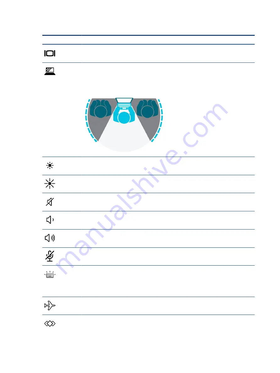
Action keys and their descriptions

Icon

Description

Switches the screen image among display devices connected to the system. For example, if a monitor is 

connected to the computer, repeatedly pressing the key alternates the screen image from computer display 

to monitor display to simultaneous display on both the computer and the monitor.

Helps prevent side-angle viewing from onlookers. If needed, decrease or increase brightness for well-lit or 

darker environments. Press the key again to turn off the privacy screen.

NOTE:

This feature is available only on select products. If the feature is not available on your computer, a 

message is displayed when you press this key.

NOTE:

To quickly turn on the highest privacy setting, press 

fn

+

p

.

Decreases the screen brightness incrementally as long as you hold down the key.

Increases the screen brightness incrementally as long as you hold down the key.

Mutes or restores speaker sound.

Decreases speaker volume incrementally while you hold down the key.

Increases speaker volume incrementally while you hold down the key.

Mutes the microphone.

Turns the keyboard backlight off or on. On select products, you can adjust the brightness of the keyboard 

backlight. Press the key repeatedly to adjust the brightness from high (when you first start up the computer), 

to low, to off. After you adjust the keyboard backlight setting, the backlight will revert to your previous 

setting each time you turn on the computer. The keyboard backlight will turn off after 30 seconds of 

inactivity. To turn the keyboard backlight back on, press any key or tap the touchpad (select products only). To 

conserve battery power, turn off this feature.

Turns the wireless feature on or off.

NOTE:

A wireless network must be set up before a wireless connection is possible.

Executes frequently used tasks. Some tasks might not be available on all products.

Opens an application, file, or website

Enters frequently used text into a permanent clipboard

18

Chapter 2  Components

Summary of Contents for Elite x2 G8

Page 1: ...Maintenance and Service Guide SUMMARY This guide provides information about spare parts removal and replacement of parts security backing up and more ...

Page 2: ...ditorial errors or omissions contained herein First Edition April 2021 Document Part Number M65100 001 Product notice This guide describes features that are common to most models Some features may not be available on your computer Not all features are available in all editions or versions of Windows Systems may require upgraded and or separately purchased hardware drivers software or BIOS update t...

Page 3: ...ct the computer air vents Use the computer only on a hard flat surface Do not allow another hard surface such as an adjoining optional printer or a soft surface such as pillows or rugs or clothing to block airflow Also do not allow the AC adapter to come into contact with the skin or a soft surface such as pillows or rugs or clothing during operation The computer and the AC adapter comply with the...

Page 4: ...d by only an authorized service provider IMPORTANT See Removal and replacement procedures for Customer Self Repair parts for details Accessing parts described in Removal and replacement procedures for authorized service provider parts can damage the computer or void your warranty iv Important notice about Customer Self Repair parts ...

Page 5: ...uter 21 Inserting a nano SIM card 21 3 Illustrated parts catalog 23 Computer major components 23 Plastics kit 26 Miscellaneous parts 27 4 Removal and replacement procedures preliminary requirements 31 Tools required 31 Service considerations 31 Plastic parts 31 Cables and connectors 31 Drive handling 31 Electrostatic discharge information 32 Generating static electricity 32 Preventing electrostati...

Page 6: ...oubleshooting steps 69 Identify the issue 69 1 Understand the issue 69 Boot up sequence 70 Failure classification 70 2 Examine the environment 72 3 Perform a visual inspection of hardware 72 4 Update BIOS and drivers 72 Manually updating BIOS and drivers 73 Remotely deploying the BIOS and drivers 73 Analyze the issue 73 5 Remove or uninstall recently added hardware software 73 6 HP Hardware Diagno...

Page 7: ...t Windows Logo hang or lockup 97 Electromagnetic Interference EMI 98 No wake up 99 Unresponsive 100 Slow performance 101 HP Smart Adapter warning message 101 Incorrect time and date 102 Display 102 Display anomalies 102 Symptom 103 Quick check 103 HP PC Hardware Diagnostics UEFI for video test 104 Display assembly diagram 104 Dead pixel 105 No video internal 105 No video external 105 DisplayPort V...

Page 8: ...blue screen error messages 130 Error message list 130 Bug check symbolic names 130 Microsoft general troubleshooting of Windows bug check codes 130 Use Windows Debugging Tool 131 Windows Software Development Kit SDK 131 Display issue pixel anomalies 135 Cable management 136 Connector types 137 Flex cable 137 Horizontal cable insertion 138 Multiple pin horizontal connector LVDS cable to display pan...

Page 9: ...he Start menu select products only 154 Downloading HP PC Hardware Diagnostics Windows 154 Downloading the latest HP PC Hardware Diagnostics Windows version from HP 154 Downloading the HP PC Hardware Diagnostics Windows from the Microsoft Store 154 Downloading HP Hardware Diagnostics Windows by product name or number select products only 155 Installing HP PC Hardware Diagnostics Windows 155 Using H...

Page 10: ...16 Recycling 170 Index 171 x ...

Page 11: ...6 MB SmartCache 15 W Intel Core i3 1125 G4 1 6 GHz turbo up to 3 9 GHz 8 MB SmartCache 15 W Intel Core i3 1115 G4 1 6 GHz turbo up to 3 9 GHz 8 MB SmartCache 15 W Display 33 02 cm 13 00 in White Light Emitting Diode WLED Ultra Wide Viewing Angle UWVA Embedded Display Port eDP 1 4 Panel Self Refresh PSR 72 of the National Television Standards Committee NTSC ultraslim touch screen Widescreen Ultra E...

Page 12: ...orldwide 5 band configured at top of panel on all models Support Fast PCIe Error Identification Supports Turbo Lite Wi Fi Supports Dynamic BIOS SAR Supports WLAN LAN WWAN switching Support HP Connection Optimizer WWAN select models only Intel XMM 7360 LTE Advanced CAT 9 SIM user accessible on side 4FF nano SIM Bluetooth Bluetooth Sensors Hall sensor Accelerometers 2 Gyroscope Magnetometer Ambient ...

Page 13: ...ead C5NS Security TPM 2 0 SLB9670 Infineon soldered down Pad fingerprint sensor select products only Preboot authentication password fingerprint Hardware enforced Firmware Protection HP Hardware Root of Trust Security lock Operating system Windows 10 Home 64 Windows 10 Home 64 Advanced Windows 10 Home 64 Advanced Single Language Windows 10 Home 64 High End Chinese Market PPP Windows 10 Home 64 Plu...

Page 14: ...e Africa Market PPP Win 10 Home 64 Single Language APAC EM PPP Win 10 Home 64 Single Language India Market PPP Win 10 Home 64 Single Language Indonesia Market PPP Win 10 Pro 64 Win 10 Pro 64 CBB 1909 Win 10 Pro 64 CBB 2004 Win 10 Pro 64 Chinese Market Win 10 Pro 64 StF MSNA Standard Serviceability End user replaceable parts AC adapter Slate only Keyboard Kickstand Pen 4 Chapter 1 Product descripti...

Page 15: ...ating software Use these instructions to find out what software is installed on your computer Right click the Start button and then select Apps and Features Right Use the illustration and table to identify the components on the right side of the computer Table 2 1 Right side components and their descriptions Component Description 1 Nano SIM card slot select products only Supports a wireless subscr...

Page 16: ...and Connects a USB device provides high speed data transfer and for select products charges small devices such as a smartphone when the computer is on or in Sleep mode NOTE Use a standard USB Type C charging cable or cable adapter purchased separately when charging a small external device and Connects a DisplayPort device that has a USB Type C connector providing display output NOTE Cables and or ...

Page 17: ...arbuds or a headset For additional safety information see the Regulatory Safety and Environmental Notices To access this guide Type HP Documentation in the taskbar search box and then select HP Documentation NOTE When a device is connected to the jack the computer speakers are disabled 2 Volume button Controls speaker volume on the computer 3 Security cable slot Attaches an optional security cable...

Page 18: ...ges NOTE Camera functions vary depending on the camera hardware and software installed on your product 7 Magnetic pen attachment areas 2 Hold an optional pen Place the pen tip up facing the top of the computer for optimal magnetic attachment NOTE For more information about the pen see the documentation provided with the pen The antennas are not visible from the outside of the computer For optimal ...

Page 19: ... identify the top components Table 2 5 Top components and their descriptions Component Description 1 Vents Enable airflow to cool internal components NOTE The computer fan starts up automatically to cool internal components and prevent overheating It is normal for the internal fan to cycle on and off during routine operation 2 Internal microphones 2 Record sound 3 Camera privacy cover Controls the...

Page 20: ...er button results in the loss of unsaved information If the computer has stopped responding and shutdown procedures are ineffective press and hold the power button for at least 4 seconds to turn off the computer To learn more about your power settings see your power options Right click the Power icon and then select Power Options 5 Power light On The computer is on Blinking The computer is in the ...

Page 21: ...ger to the fingerprint reader IMPORTANT To prevent fingerprint logon issues make sure when you register your fingerprint that all sides of your finger are registered by the fingerprint reader IMPORTANT To verify that your computer supports fingerprint reader sign in type Sign in options in the taskbar search box and follow the on screen instructions If Fingerprint reader is not listed as an option...

Page 22: ... a midway point 1 of approximately 52 or at full stopping point 2 of about 165 3 To close the kickstand push the kickstand against the bottom of the computer until it is flush with the bottom Keyboard area select products only Keyboards can vary by language Connecting the keyboard Use these steps to connect the keyboard to the computer 12 Chapter 2 Components ...

Page 23: ...To connect the keyboard lower the computer onto the keyboard until the connectors click into place Removing the keyboard Use these steps to remove the keyboard from the computer Removing the keyboard 13 ...

Page 24: ...t touchpad settings and gestures 1 Type touchpad settings in the taskbar search box and then press enter 2 Choose a setting Turning on the touchpad Follow these steps to turn on the touchpad 1 Type touchpad settings in the taskbar search box and then press enter 2 Using an external mouse click the Touchpad button If you are not using an external mouse press the Tab key repeatedly until the pointer...

Page 25: ...cription 1 Touchpad zone Reads your finger gestures to move the pointer or activate items on the screen 2 Left touchpad button Functions like the left button on an external mouse 3 Right touchpad button Functions like the right button on an external mouse Lights Use the illustration and table to identify the lights on the computer Touchpad components 15 ...

Page 26: ...lock light On The fn key is locked For more information see Hot keys select products only on page 19 3 Mute light On Computer sound is off Off Computer sound is on 4 Microphone mute light On Microphone is off Off Microphone is on 5 Num lk light On Num lk is on Special keys Use the illustration and table to identify the special keys 16 Chapter 2 Components ...

Page 27: ...perimposed over the keyboard alphabet keys When num lk is pressed the keypad can be used like an external numeric keypad Each key on the keypad performs the function indicated by the icon in the upper right corner of the key NOTE If the keypad function is active when the computer is turned off that function is reinstated when the computer is turned back on 6 num lk key Turns the embedded numeric k...

Page 28: ... down the key Mutes or restores speaker sound Decreases speaker volume incrementally while you hold down the key Increases speaker volume incrementally while you hold down the key Mutes the microphone Turns the keyboard backlight off or on On select products you can adjust the brightness of the keyboard backlight Press the key repeatedly to adjust the brightness from high when you first start up t...

Page 29: ...iption C Turns on scroll lock E Turns on the insert function R Breaks the operation S Sends a programing query W Pauses the operation Labels The labels affixed to the computer provide information you might need when you troubleshoot system problems or travel internationally with the computer Labels might be in paper form or imprinted on the product IMPORTANT Check the following locations for the l...

Page 30: ...r 2 Product ID 3 HP product name Table 2 13 Service label components Component 1 HP product name 2 Product ID 3 Serial number 4 Warranty period Table 2 14 Service label components Component 1 HP product name 2 Warranty period 3 Product ID 20 Chapter 2 Components ...

Page 31: ...or connectors use minimal force when inserting or removing a SIM card Determining the correct SIM card size for your computer Before purchasing a SIM card follow these instructions to determine the correct SIM card size for your computer 1 Go to http www hp com support and then search for your computer by product name or number 2 Select Product Information 3 Refer to the listed options to determin...

Page 32: ...5 Replace the tray in the computer Press in gently on the tray 4 until it is firmly seated To remove the SIM card reverse these steps 22 Chapter 2 Components ...

Page 33: ...TE HP continually improves and changes product parts For complete and current information about supported parts for your computer go to http partsurfer hp com select your country or region and then follow the on screen instructions NOTE Details about your computer including model serial number product key and length of warranty are on the service tag at the bottom of your computer Illustrated part...

Page 34: ...er 1 Display panel touch screen NOTE Display spare parts are available as subcomponents not as whole units Display subcomponent spare parts are available WUXGA M51632 001 WUXGA privacy M51634 001 3k 2k M51633 001 2 Back cover M51636 001 3 Top cover keyboard 24 Chapter 3 Illustrated parts catalog ...

Page 35: ...rating systems xxxxxx 601 Windows operating system Intel Core i3 1115 G4 processor and 8 GB of system memory with thermal material M51650 001 Intel Core i3 1125 G4 processor and 8 GB of system memory with thermal material M75287 001 Intel Core i5 1135 G7 processor and 16 GB of system memory with thermal material M51651 001 Intel Core i5 1135 G7 processor and 8 GB of system memory with thermal mate...

Page 36: ...7422 001 14 Kickstand L67409 001 15 Kickstand hinges M51637 001 16 Camera module HD camera 8 MP M75415 001 IR camera 2 MP L67412 001 17 Volume board M73529 001 18 IR LED and cable M75416 001 19 USB Type C bracket L67409 001 SIM board M51642 001 SIM board cable L67423 001 Microphone cable L67421 001 Plastics kit To identify the plastics kit use this illustration and table Table 3 2 Plastics kit des...

Page 37: ...r rubber and battery rubber M51660 001 Solid state drive absorber M51635 001 IVO panel absorber M51661 001 WLAN cover kit M51647 001 WWAN cover kit M51648 001 HP Collaboration Keyboards For use in Belgium M51231 A41 For use in Brazil M51231 201 For use in Bulgaria M51231 261 For use in Canada M51231 DB1 For use in the Czech Republic and Slovakia M51231 FL1 For use in Denmark M51231 081 For use in ...

Page 38: ...in Sweden and Finland M51231 B71 For use in Switzerland M51231 BG1 For use in Taiwan M51231 AB1 For use in Thailand M51231 281 For use in Turkey M51231 141 For use in the United Kingdom M51231 031 For use in the Ukraine M51231 BD1 For use in the United States M51231 001 Power cord duckhead C5 1 0 m 3 3 ft For use in North America L50818 002 For use in Japan L33157 001 For use in Korea L50818 001 P...

Page 39: ... Denmark L22334 001 Europe L22321 001 India L22624 001 Israel L22323 001 Italy L30813 001 Japan L22330 001 Korea L22328 001 North America L22319 001 People s Republic of China L22341 001 Saudi Arabia L22337 001 Switzerland L22336 001 Taiwan L22342 001 United Kingdom L22320 001 United Kingdom L22332 001 Power cords C5 1 0 m 3 3 ft FDH sticker premium Argentina L36815 001 Australia L36816 001 Brazil...

Page 40: ... L19360 002 India L19363 002 Israel L19362 002 Italy L19364 002 Japan L19365 002 Korea L19366 002 North America L19367 002 People s Republic of China L19368 002 Saudi Arabia L19369 002 Switzerland L19370 002 Taiwan L19372 002 United Kingdom L19373 002 Power cords C5 1 0 m 3 3 ft ADP bundle with cord Thailand L22338 001 Thailand L19371 001 Thailand L36826 001 Power cord duckhead C5 1 0 m 3 3 ft ADP...

Page 41: ...ng the computer be sure that cables are placed in their proper locations during the reassembly process Improper cable placement can damage the computer Apply only the tension required to unseat or seat the cables during removal and insertion Handle cables by the connector whenever possible In all cases avoid bending twisting or tearing cables Be sure that cables are routed so that they cannot be c...

Page 42: ...ctly throughout a normal cycle The device might function normally for a while but it has been degraded in the internal layers reducing its life expectancy Networks built into many integrated circuits provide some protection but in many cases the discharge contains enough power to alter device parameters or melt silicon junctions IMPORTANT To prevent damage to the device when you remove or install ...

Page 43: ...ners or packaging Keep electrostatic sensitive parts in their containers until they arrive at static free stations Place items on a grounded surface before removing them from their container Always be properly grounded when touching a sensitive component or assembly Avoid contact with pins leads or circuitry Place reusable electrostatic sensitive parts from assemblies in protective packaging or co...

Page 44: ...n fixtures must directly contact dissipative surfaces Keep the work area free of nonconductive materials such as ordinary plastic assembly aids and polystyrene foam Use conductive field service tools such as cutters screwdrivers and vacuums Avoid contact with pins leads or circuitry Recommended materials and equipment HP recommends certain materials and equipment to prevent static electricity Anti...

Page 45: ...age 35 for the recommended steps to clean the high touch external surfaces on your computer After you remove the dirt and debris you can also clean the surfaces with a disinfectant See Cleaning your computer with a disinfectant on page 36 for guidelines to help prevent the spread of harmful bacteria and viruses Removing dirt and debris from your computer Here are the recommended steps to clean dir...

Page 46: ...sinfectant A disinfectant that is within HP s cleaning guidelines is an alcohol solution consisting of 70 isopropyl alcohol and 30 water This solution is also known as rubbing alcohol and is sold in most stores Follow these steps when disinfecting high touch external surfaces on your computer 1 Wear disposable gloves made of latex or nitrile gloves if you are latex sensitive when cleaning the surf...

Page 47: ...e Removing dirt and debris from your computer on page 35 for the recommended steps to clean the high touch external surfaces on your computer After you remove the dirt and debris you can also clean the surfaces with a disinfectant See Cleaning your computer with a disinfectant on page 36 for sanitizing guidelines to help prevent the spread of harmful bacteria and viruses Packaging and transporting...

Page 48: ...uter and allow the operating system to open 2 Click the search icon in the taskbar 3 Type Event Viewer and then press enter 4 Select the log from the left panel Details display in the right panel Chrome 1 Go to support google com chrome 2 Search collect Chrome device logs Technical bulletins To locate technical bulletins 1 Go to www hp com 2 Place the cursor over Problem solving to display more op...

Page 49: ... 4 3 Support information locations continued Service consideration Path to access information 3 Near the bottom of the window select Notebook PCs and the select your location Accessing support information 39 ...

Page 50: ... the on screen instructions You must remove replace or loosen as many as 44 screws when you service Customer Self Repair parts Make special note of each screw size and location during removal and replacement Preparation for disassembly To prepare to disassemble the computer use these steps See Removal and replacement procedures preliminary requirements on page 31 for initial safety procedures 1 Tu...

Page 51: ... Torx T5 2 0 3 5 screws from each side of the kickstand 1 2 Pull the sides of the kickstand away from the computer 2 and then remove the kickstand 3 To replace the kickstand reverse the removal procedures Kickstand 41 ...

Page 52: ...oosen as many as xx screws when you service the parts described in this chapter Make special note of each screw size and location during removal and replacement Preparation for disassembly To remove and replace computer components use these procedures See Removal and replacement procedures preliminary requirements on page 31 for initial safety procedures 1 Turn off the computer If you are unsure w...

Page 53: ...nel IMPORTANT Cables connect the panel to the computer Be careful not to disconnect the cables when rotating the panel Be careful when opening to avoid tearing cables Be sure to open from the top Before removing the display panel follow these steps Prepare the computer for disassembly see Preparation for disassembly on page 40 Remove the display panel 1 Remove the two Torx T5 2 0 3 5 screws from e...

Page 54: ... lever to lock the cup 2 4 To remove the panel evenly secure the suction tool to each corner of the display panel and then pull the suction tool handle 1 4 to release each section of the panel from the computer 44 Chapter 6 Removal and replacement procedures for authorized service provider parts ...

Page 55: ...the panel 1 7 Disconnect the battery cable 2 from the system board IMPORTANT Be careful when opening to avoid tearing cables Be sure to open from the top 8 Remove the tape from the display cable connector 3 and then disconnect the display cable 4 from the system board Display panel 45 ...

Page 56: ...n Table 6 2 Battery description and part number Description Spare part number Battery 2 cell 47 Wh M51660 001 WARNING To avoid personal injury and damage to the product Do not puncture twist or crack the battery Do not cause an external puncture or rupture to the battery They can cause a short inside the battery which can result in battery thermal runaway 46 Chapter 6 Removal and replacement proce...

Page 57: ... for disassembly see Preparation for disassembly on page 40 2 Remove the display panel see Display panel on page 42 WARNING To reduce potential safety issues use only the user replaceable battery provided with the computer a replacement battery provided by HP or a compatible battery purchased from HP IMPORTANT Removing a battery that is the sole power source for the computer can cause loss of info...

Page 58: ...05 001 512 GB SATA 3 self encrypting drive SED Opal 2 TLC L674021 001 512 GB PCIe TLC L67403 001 512 GB PCIe L67404 001 256 GB SATA 3 self encrypting drive SED Opal 2 TLC L67398 001 256 GB PCIe TLC L67399 001 256 GB PCIe L67400 001 128 GB SATA 3 TLC L67398 001 Before removing the solid state drive follow these steps 1 Prepare the computer for disassembly see Preparation for disassembly on page 40 ...

Page 59: ... disassemble the SIM card holder board use these procedures and illustrations Table 6 4 SIM card holder board descriptions and part numbers Description Spare part number SIM card holder board M51642 001 SIM card holder cable L67423 001 Before removing the SIM card holder board follow these steps 1 Prepare the computer for disassembly see Preparation for disassembly on page 40 2 Remove the display ...

Page 60: ...Phillips M1 4 1 6 screws 3 that secure the board 5 Remove the board from the computer 4 Reverse this procedure replace the SIM card holder board Kickstand hinges To remove the kickstand hinge use this procedure and illustration Table 6 5 Kickstand hinges description and part number Description Spare part number Kickstand hinges L67409 001 50 Chapter 6 Removal and replacement procedures for authori...

Page 61: ...ocedure and illustration Table 6 6 WWAN module descriptions and part numbers Description Spare part number Intel XMM 7360 LTE w GPS M 2 L70670 005 WWAN kit M51648 001 IMPORTANT To prevent an unresponsive system replace the wireless module only with a wireless module authorized for use in the computer by the governmental agency that regulates wireless devices in your country or region If you replac...

Page 62: ...ables 2 3 Using a Phillips 0 screwdriver remove the Phillips M1 4 1 6 screw 3 and then remove the module 4 NOTE Models have either one or two WLAN antennas On models with two antennas the 1 white WLAN antenna cable connects to the WLAN module 1 Main terminal The 2 black WLAN antenna cable connects to the WLAN module 1 Aux terminal 4 If the WWAN antenna is not connected to the terminal on the WWAN ...

Page 63: ... the computer for disassembly see Preparation for disassembly on page 40 2 Remove the display panel see Display panel on page 42 3 Remove the battery see Battery on page 46 Remove the POGO connector and cable 1 Disconnect the POGO cable from the ZIF connector on the system board 1 2 Remove the two Phillips M1 4 2 5 screws 2 3 Peel the cable up to disengage the adhesive that secures it to the compu...

Page 64: ...are the computer for disassembly see Preparation for disassembly on page 40 Remove the camera module 1 Disconnect the four cables from the ZIF connectors on the camera module 1 2 Using a Phillips 0 screwdriver remove the two Phillips M1 4 2 5 screws 2 that secure the module to the computer and then remove the module from the computer 3 3 If you need to remove the IR LED cable from the camera modul...

Page 65: ...is procedure and illustration Table 6 9 Speakers and antennas description and part number Description Spare part number Antennas WWAN L67432 001 Antennas WWAN M51641 001 Speakers with WLAN antennas M51638 001 Speakers with WWAN antennas M51639 001 Speakers with GPS antennas L67429 001 Speakers with WWAN antennas for HP INT XMM 7360 LTE w GPS M 2 L70670 005 Before removing the speakers follow these...

Page 66: ...connect the camera cables from the system board 4 to remove the speaker antennas that run underneath them 5 Lift the WLAN antennas from the heat sink 5 6 Lift the protective strips from the heat sink near the WWAN module 6 7 Use a tool to release the left speaker from the adhesive that secures it 7 and remove the speakers from the computer Reverse this procedure to install the speakers and antenna...

Page 67: ...nstalling the antennas and speakers by noting the location of 1 computer notches and 2 speaker snaps 9 To install the number 1 antenna cable insert the cable into the slots 1 and 2 and then place the contact over the cable 3 Speakers with antennas 57 ...

Page 68: ... 1 and 2 and then place the contact over the cables 3 11 When installing the right speaker lift the right side of the speaker 1 and insert the notch on the speaker into the snap in the computer 2 58 Chapter 6 Removal and replacement procedures for authorized service provider parts ...

Page 69: ...ese steps 1 Prepare the computer for disassembly see Preparation for disassembly on page 40 2 Remove the display panel see Display panel on page 42 3 Remove the battery see Battery on page 46 4 Remove the speakers see Speakers with antennas on page 55 Remove the antennas 1 Disconnect each antenna cable from the system board 1 2 Using a tweezer remove each antenna from the connectors on the bottom ...

Page 70: ...repare the computer for disassembly see Preparation for disassembly on page 40 2 Remove the display panel see Display panel on page 42 3 Disconnect the battery cable from the system board see Battery on page 46 Remove the power button board 1 Disconnect the power button board cable from the system board 1 2 Remove the Phillips M1 4 2 5 screw 2 that secures the power button board to the computer 3 ...

Page 71: ...le L67419 001 Before removing the volume board follow these steps 1 Prepare the computer for disassembly see Preparation for disassembly on page 40 2 Remove the display panel see Display panel on page 42 3 Disconnect the battery cable from the system board see Battery on page 46 4 Remove the speakers see Speakers with antennas on page 55 Remove the volume board 1 Disconnect the volume board cable ...

Page 72: ...speaker must be removed before removing the fingerprint reader board Before removing the fingerprint reader board follow these steps 1 Prepare the computer for disassembly see Preparation for disassembly on page 40 2 Remove the display panel see Display panel on page 42 3 Disconnect the battery cable from the system board see Battery on page 46 4 Disconnect the left speaker see Speakers with anten...

Page 73: ...5 G7 processor and 16 GB of system memory with thermal M51651 001 Intel Core i5 1135 G7 processor and 8 GB of system memory with thermal M51652 001 Intel Core i5 1135 G7 processor and 16 GB of system memory OSR with thermal M51657 001 Intel Core i5 1145 G7 processor and 16 GB of system memory OSR with thermal M51653 001 Intel Core i5 1145 G7 processor and 8 GB of system memory OSR with thermal M51...

Page 74: ...may need to lift the left speaker Hall effect board cable 5 To reconnect this cable to the system board you may need to lift the left speaker Headphone power button board cable 6 To reconnect this cable to the system board you may need to lift the left speaker Speaker cable 7 To reconnect this cable to the system board you may need to lift the left speaker Microphone cable 8 Camera cable 9 Camera ...

Page 75: ...ype C bracket 4 6 Remove the four Phillips M1 4 1 6 screws 2 that secure the system board to the computer 5 and then remove the system board from the computer 6 A BIOS board is connected to the system board Do not remove this board when removing the system board Reverse this procedure to install the system board Do not remove the BIOS board after removing the system board System board 65 ...

Page 76: ... 46 NOTE The heat sink is spared with the system board Take care when removing this module as it can be easily damaged Remove the heat sink 1 Disconnect the fan cable from the system board 1 2 In the order indicated on the heat sink remove the four captive Phillips M1 4 1 6 screws 2 that secure the heat sink to the computer NOTE Make sure the grounding clips align with the heat sink for proper rei...

Page 77: ... is removed Replacement thermal material is included with the heat sink and system board spare part kits The following illustration shows the replacement thermal material locations Thermal paste is used on the system board components 1 2 and 4 with pads on the heat sink areas 3 that service them Reverse this procedure to install the heat sink and fan Heat sink with fan 67 ...

Page 78: ... discharge precautions Discharge static electricity by briefly touching a grounded metal object before you begin Work on a static free mat Wear a static strap to ensure that any accumulated electrostatic charge is discharged from your body to the ground Create a common ground for the equipment that you are working on by connecting the static free mat static strap and peripheral units to that piece...

Page 79: ...lve a memory issue using the HP PC Diagnostics UEFI tool in step 6 you can then move on to step 10 to reseat the memory into its memory slot NOTE You can ignore troubleshooting steps that do not apply to your issue Table 7 2 Troubleshooting methodology and general troubleshooting steps Identify issue Analyze issue Resolve issue Verify solution 1 Understand the issue on page 69 2 Examine the enviro...

Page 80: ...formance operating system System boots to operating system and Windows logo screen appears Common issues hangs blue screen distorted video driver conflict slow performance display issue dead pixel I O issue no speaker sound wireless audio unavailable noise See Analyze the issue on page 73 table for detailed troubleshooting information Failure classification Failure classification is a breakdown of...

Page 81: ...n information Table 7 4 Failure classification by boot up sequence 1 Power on 2 POST 3 Performance 1 No power on page 85 2 Intermittent power on shutdown reboot on page 87a 3 AC adapter issue on page 88 4 Battery not recognized not charging on page 88 5 Battery discharges too fast on page 90 6 Burnt smell on page 91 1 No video with power on page 91 2 Blinking lights on page 92 3 Diagnostic error m...

Page 82: ...onnections are loose Confirm that power sources are good such as AC outlet or adapter 110 V 220 V ac power strip Test with a verified working AC outlet Check for compatibility issues between the computer and third party devices peripherals uncertified devices incompatible hardware for instance Mac OS device Incompatibility can result in blue screen errors improper operation and so on Isolate the c...

Page 83: ...rted recently it may be related to the recent addition of hardware or software A good method to determine the root cause is to remove recently added components or uninstall applications one at a time and restart the computer when necessary IMPORTANT After you have completed the process of uninstalling hardware or software and are ready to reinstall be sure that the new device seated properly and a...

Page 84: ...the computer s hardware to verify that everything is functioning properly If your system won t boot into Windows try the Quick System Test For more comprehensive testing use the Extensive System Test option If the System Test did not detect a hardware problem continue with the Component Tests Component Tests focus on selected hardware components in your computer Firmware Management update your com...

Page 85: ...quick to try whereas BCU takes extra time and effort HP Image Diagnostic Tool Available to HP Authorized Support Partners ASPs and users this tool collects information about the current state of the computer including product serial number platform and BIOS information and information about user installed software and hardware components Access this tool at ftp ftp hp com pub idr ImageDiags HP enc...

Page 86: ...ns Component Description Power button When the computer is off press the button to turn on the computer When the computer is on press the button briefly to initiate Sleep Windows or Suspend Linux When the computer is in the Sleep state press the button briefly to exit Sleep Windows or Suspend Linux When the computer is in Hibernation press the button briefly to exit Hibernation IMPORTANT Pressing ...

Page 87: ...xecuting code Caps and num lk lights 2 blinks BIOS recovery code unable to find valid BIOS recovery image Caps and num lk lights 3 blinks Memory module error Caps and num lk lights 4 blinks Graphics controller error Caps and num lk lights 5 blinks System board error Caps and num lk lights 6 blinks Intel Trusted Execution Technology TXT Error Caps and num lk lights 7 blinks Sure Start unable to fin...

Page 88: ...icates that the primary battery has very low capacity Search for support documentation at http www hp com support for details on using the HP Support Assistant to verify the battery capacity and if necessary order a replacement Wireless Modules Not installed or responding 701 Reseat the wireless LAN adapter module and antennas Because seating or reseating a wireless LAN adapter is unique to each c...

Page 89: ...mputer but do not connect any of the peripheral devices 8 Press the power button to turn on the computer 9 If a startup menu appears use the arrow keys to select Start Windows Normally and then press the enter key 10 After reconnecting each of the peripheral devices run Windows Update and HP Support Assistant to update all device drivers CMOS refers to the battery powered semiconductor chip locate...

Page 90: ...rror Reseating the wireless module and antenna cable can resolve a wireless connection issue For field replaceable units FRUs authorized service providers can try the following steps For more information see Removal and replacement procedures for authorized service provider parts on page 42 Reseating the fan cable can fix POST error 90B no fan detected issue see POST error messages and user action...

Page 91: ...disconnect all connections internal keyboard display discrete GPU hard drive or solid state drive daughterboards and so on to achieve the essential hardware configuration Do not disassemble the system board from its enclosure at this time Reverse the previous procedure by reinstalling each piece of hardware removed one piece at a time and testing your computer after each installation Because your ...

Page 92: ...y hardware Review Table 7 2 Troubleshooting methodology and general troubleshooting steps on page 69 for appropriate troubleshooting steps IMPORTANT System board failure is not common Do not replace the system board until you have tried all other troubleshooting options NOTE Determine whether a previous service case might be related to the current problem For example a fan detection issue could be...

Page 93: ...se steps provide simple useful checks that you can perform when troubleshooting TIP If you have installed an operating system other than the factory installed operating system go to http www hp com go quickspecs and verify that it is supported on your system 1 Be sure that the computer is plugged into a working AC outlet 2 Be sure that power is connected to the docking station if you use a dock 3 ...

Page 94: ...re might be a problem with the network plug or cable 7 If hardware has recently been installed remove it and determine whether the computer functions properly 8 If software has recently been installed uninstall it and determine whether the computer functions properly 9 If the screen is blank confirm the display choice by pressing Windows logo p and set to screen only Or plug an external monitor in...

Page 95: ...Possible causes Failed power input to the computer external power source AC adapter faulty battery Bad connection to the computer bad power button power connector Defective parts memory hard drive graphics or failed system board Troubleshooting steps Perform quick check Remove all external devices including docking station Verify external power source 2 Examine the environment on page 72 Perform a...

Page 96: ...voltage 1 Measure DC voltage output which should be approximately 19 5 V dc Acceptable voltage range is from 18 5 to 20 5 V dc 2 If the DC voltage is out of range replace the AC adapter NOTE This action requires a digital voltmeter NOTE Select models include a power cable between the system board and chassis power connector Verify power button power connector 1 Be sure that power button is not stu...

Page 97: ...Visually check power ports on both AC adapter and computer sides 2 Inspect power sources a Verify that the AC adapter is working correctly Use a confirmed working adapter to test b Verify that battery is not depleted while system is in the Sleep state Test with a confirmed working battery The following steps are for authorized providers or technicians 1 Follow actions in No power on page 85 a Be s...

Page 98: ...essage on page 101 for further information Verify AC adapter 1 Remove working battery 2 Verify that AC adapter is compatible with product Verify that part number is for this computer if possible 3 Inspect AC adapter and power cord for physical damage bent middle ID pin 4 Plug in AC adapter and power the computer without battery 5 Inspect the power port on computer side for any damage dust debris 6...

Page 99: ...on page 79 Verify AC adapter 1 Determine whether the computer needs the AC adapter to boot and operate Sometimes an intermittently bad AC adapter and loose connection between adapter and computer results in inability to charge battery which causes short run time 2 Inspect AC adapter to verify that it is functioning 3 Test with a working AC adapter and confirm whether battery is charging 4 Be sure ...

Page 100: ...rm whether issue is hardware related 1 Review battery power plans in Control Panel Power Options that may consume more energy and discharge battery faster Resetting default to Power Saver option can conserve battery power 2 Determine whether any graphics are processing 3 Verify battery maintenance and operations Leaving the battery at a high level of charge in a high temperature environment for ex...

Page 101: ... sources internally after disassembling chassis such as burnt or damaged components 2 If the issue persists replace boards AC adapter and battery for safety concern and report issues to HP POST Use the following sections to troubleshoot Power on Self Test issues No video with power Use this information to troubleshoot video issues Table 7 15 Issues possible causes and fixes Items Procedures Sympto...

Page 102: ...ble connection on system board 2 Reseat display cable connection on display panel side 3 Examine and reseat major components such as hard drive and memory 4 Test with minimum configuration 11 Test with minimum configuration on page 80 by removing hard drive to isolate operating system issues and testing video in F10 Setup 5 If video is present restart and retest the computer 6 If video is present ...

Page 103: ...ay be a problem with the instruction being sent from the BIOS to a hardware component for example keyboard failures or incompatible hardware Can usually be resolved by installing updated firmware for the component Troubleshooting steps 1 See 7 Status lights blinking light codes troubleshooting lights and POST error messages on page 76 for corrective actions An example of a POST error message might...

Page 104: ...ations Make sure that all the necessary device drivers are installed If an operating system other than the factory operating system is installed check whether the operating system is supported and the application is certified for the version of the operating system Intermittent shutdown Use this information to troubleshoot shutdown issues Table 7 19 Issues possible causes and fixes Items Procedure...

Page 105: ...eat sink fan fin or vent d Test with a verified working fan e Remove old thermal compound and pads and replace with new compound and pads 2 Verify thermal solution Use Thermal Monitor tool available only to authorized service providers technicians to perform stress test processor and GPU 6 HP Hardware Diagnostics and Tools on page 73 and verify that thermal sensors are within limits after thermal ...

Page 106: ... information search for HP Troubleshooting Error Messages on a blue screen at http www hp com Overview of general troubleshooting steps for a blue screen error 1 Note the blue screen error message and what activity was performed at the time 2 Perform a hard reset 8 Hard reset on page 78 after disconnecting all external peripherals 3 Reset BIOS to default 9 Soft reset Default Settings on page 79 to...

Page 107: ...ate d Check for specific STOP error by analyzing Crash Dump retrieved via a bootable USB See Use Windows Debugging Tool on page 131 e Restore computer using System Recovery or image backup to factory settings 10 Test with essential hardware configuration 11 Test with minimum configuration on page 80 with a verified working operating system for instance USB Windows To Go if available to isolate the...

Page 108: ...ardware software on page 73 6 Reseat cables and connections 10 Reseat cables and connections on page 80 7 Start Windows in safe mode 11 Test with minimum configuration on page 80 8 Use Startup Repair Windows to fix Windows damaged files 9 Test with essential hardware configuration 11 Test with minimum configuration on page 80 with a verified working operating system for instance USB Windows To Go ...

Page 109: ...Table 7 23 Issues possible causes and fixes Items Procedures Symptoms When resuming from a power management state the computer may display Blank screen Some light activity Possible causes Power saving mode multiple display setting Troubleshooting steps 1 Verify that front power light 7 Status lights blinking light codes troubleshooting lights and POST error messages on page 76 is blinking indicati...

Page 110: ...s in a power saving state but the screen image may actually appear on an external display device in the docking configuration Unresponsive Use this information to troubleshoot issues with responsiveness Table 7 24 Issues possible causes and fixes Items Procedures Symptom Unresponsive Possible causes Program in use has stopped responding to commands Troubleshooting steps 1 If possible use the Windo...

Page 111: ...reate more space on the hard drive Microsoft recommends at least 200 MB to sync system files 2 Perform disk defragmentation to consolidate fragmented data on the hard drive so it works more efficiently Tips See Routine maintenance for performance improvement on page 129 See http windows microsoft com en us windows 8 free up disk space See http windows microsoft com en us windows optimize windows b...

Page 112: ...r with systems that have a discrete video subsystem a video balance mode may occur to further balance the power needs of the system Because system processor functions always have priority over battery charging charging delays occur first Incorrect time and date Use the following information to troubleshoot time and date issues Table 7 27 Issues possible causes and fixes Item Procedure Symptom Inco...

Page 113: ... hot because of thermal issue Cracked screen image physical damage Light leakage bleeding Contact support for assistance Humming noise due to frequency settings Contact support for assistance Table 7 28 Display anomaly illustrations Display anomalies Cracked screen Cracked image Blurred image Dead pixel Vertical lines Horizontal lines Quick check Use these steps to check the display Visually exami...

Page 114: ...cs UEFI 6 HP Hardware Diagnostics and Tools on page 73 when the computer is at boot press the f2 key select Component Tests and then select Video There are three options Video Memory Check to test video memory Palette Check to test the three video color components red green blue Dead Pixel Check to check dead pixels in eight different colors Dead Pixel Check is available with the HP PC Diagnostics...

Page 115: ...for the HP dead pixel policy No video internal Use this information to troubleshoot video issues Table 7 29 Issues possible causes and fixes Items Procedures Symptoms No internal video with certain programs for example video intensive games Possible causes Display resolution brightness faulty lid switch running a program requiring a higher resolution than the display screen can support Faulty lid ...

Page 116: ... then force output to external video by closing the notebook lid or pressing fn f4 to switch screen output DisplayPort VGA Use this information to troubleshoot DisplayPort and VGA issues See No video external on page 105 HDMI Use this information to troubleshoot HDMI issues Table 7 31 Issues possible causes and fixes Items Procedures Symptoms Display issue Sound issue Possible causes Cable connect...

Page 117: ...h for HP ZBook Thunderbolt 3 Dock User Guide 4 If the screen image is distorted try a DP to VGA adapter Connect the adapter to each DisplayPort and VGA port of the dock 5 Test the monitor via internal ports such as VGA DP HDMI and others 6 Verify that dock connectors of the notebook and the dock are clean without dust debris for example using air duster 7 Ideally use a verified working operating s...

Page 118: ...cable If moving cables does not affect the image the monitor has an issue Test with a confirmed working monitor Touch screen Use this information to troubleshoot touch screen issues Table 7 34 Issues possible causes and fixes Items Procedures Symptoms Unresponsive Inaccurate Possible causes Dirt and smudge driver touch display configuration power management Troubleshooting steps Quick check Turn o...

Page 119: ...nal devices are supported and compliant for example USB Type C Thunderbolt 3 PCI Express If you have problems with external devices not provided by HP contact device manufacturers for compatibility and latest drivers before troubleshooting for example USB devices Thunderbolt devices PCI express card reader VGA display HDMI monitors speakers Be sure I O devices are properly inserted into the I O po...

Page 120: ...ables are fully inserted and in good condition The following steps are for authorized providers and technicians 1 Verify whether keyboard flex cable is in good condition no delamination or torn cable end no missing or cracked tracks pads 2 Verify that keyboard flex cable ends are fully inserted and aligned with connectors on system board and those connector tabs are properly closed Reseat cables 3...

Page 121: ...eps NOTE Not all notebook computers have backlit keyboards A keyboard function key lets you turn the light on and off Verify whether backlit feature is not disabled by pressing a combination of fn backlit key The following steps are for authorized providers or technicians 1 Verify whether backlight flex cables are in good condition no delamination or torn cable end no missing or cracked tracks or ...

Page 122: ...RJ 45 jack Use this information to troubleshoot network issues Table 7 39 Issues possible causes and fixes Items Procedures Symptoms Unable to find networks yellow bang Connection dropouts Slow performance Possible causes Network source cable connection RJ 45 network jack driver settings Troubleshooting steps Quick Check verify the network status lights that supposed to flash when there is network...

Page 123: ...teps 1 Update to the latest driver and utility 2 Check with network service provider for signal coverage 3 Be sure signal strength is good 4 Be sure that your service is active The following steps are for authorized providers or technicians Verify module and antenna cable connections are not loose Verify antenna cables are properly connected to the correct terminals For example the antenna cable l...

Page 124: ...e USB key to be sure USB ports are functional 7 Test the USB device on a verified working computer to be sure the USB device is not malfunctioning Smart card reader Use this information to troubleshoot smart card reader issues Table 7 43 Issues possible causes and fixes Items Procedures Symptoms Not recognized Unable to write Possible causes Physical damage incorrect insertion dirt driver malfunct...

Page 125: ...ecognized malfunctioning hardware electronic interference Troubleshooting steps 1 Remove any device connected to the audio jack to enable the internal speaker 2 Close all open programs 3 Adjust volume by pressing fn f6 or f7 Be sure that volume button light is not amber mute or Adjust Windows volume control by clicking the speaker icon on the Windows taskbar Be sure that the sound is not muted 4 V...

Page 126: ... 3 Adjust volume by pressing fn f6 or f7 Be sure that volume button light is not amber mute or Adjust Windows volume control by clicking the speaker icon on the Windows taskbar Be sure that the sound is not muted 4 Check for possible interference devices nearby that might affect the audio cell phone or portable communications handset Thunderbolt TB Use this information to troubleshoot Thunderbolt ...

Page 127: ... before troubleshooting the drive Before contacting support HP recommends that you run a drive HDD SSD M 2 drive test using the HP PC Hardware Diagnostics UEFI tool on the suspected failed drive Diagnose the hard drive using BIOS Diagnostics built in the shipping image or an external USB http www8 hp com us en campaigns hpsupportassistant pc diags html jumpid va_r602_us en any pps pl_ot_ob HP reco...

Page 128: ...eset BIOS to default 3 Verify hard drive connection and flex cable Reseat hard drive and cable connection For multiple storage devices keep the primary drive with the operating system and remove other devices 4 Use the HP Hardware Diagnostics tool to verify that the drive is recognized and test it 5 If the hard drive fails diagnostics record failure and have the drive replaced 6 Identify when the ...

Page 129: ...move other devices 4 Use PC Hardware Diagnostics tool to test Record failure code and have the hard drive replaced 5 If there is no error reinstall the operating system using HP Restore 6 Test with a verified working operating system hard drive if available Note If there is a hard drive POST error message see POST error messages and user actions on page 127 Read write error Use this information to...

Page 130: ...n SSD Tips tricks For optimal system performance place your operating system and all of your most commonly used applications and files on the fastest hard drive solid state drive and fastest areas on the drive primary partition of 200 GB max See Routine maintenance for performance improvement on page 129 Blue screen BSOD error A faulty hard drive can cause a blue screen error Perform the drive tes...

Page 131: ... For optimal system performance place your operating system and all of your most commonly used applications and files on the fastest hard drive or solid state drive and on the fastest areas on the drive primary partition of 200 GB max See Routine maintenance for performance improvement on page 129 Mechanical Use this information to troubleshoot mechanical issues Noise sound Use this information to...

Page 132: ... fan Table 7 52 Issues possible causes and fixes Items Procedures Symptoms Fan never stops running Generates heat Decreased computer performance Possible causes BIOS not up to date Thermal condition fan air flow fan might not be defective but must run constantly to remove excess heat generated by electrical components Inappropriate configuration Troubleshooting steps General actions 1 Verify wheth...

Page 133: ...s part of thermal solution including heat sink heat sink fin muffler and thermal grease Fan replacement requires reboot and fan function verification using HP PC Hardware Diagnostics UEFI tool For more information see the following links http support hp com us en document c01007591 https support hp com us en document c01657439 Thermal shutdown hot Use this information to troubleshoot a thermal shu...

Page 134: ...s serviced Note See https support hp com us en document c01657439 Additional information The following sections provide additional information that you can use during the troubleshooting process Acronyms These acronyms are used in this chapter Blue screen BSOD A Windows error screen that can occur if a problem causes your computer to shut down or restart unexpectedly When you experience this type ...

Page 135: ...and num lk lights 4 blinks Graphics controller error Caps and num lk lights 5 blinks System board error Caps and num lk lights 6 blinks Intel Trusted Execution Technology TXT Error Caps and num lk lights 7 blinks Sure Start unable to find valid BIOS Boot Block image Caps and num lk lights 8 blinks Sure Start has identified a problem Manual Recovery Policy Set Processor not executing code This comp...

Page 136: ...controller initialization problem resulting in a failed startup This issue might be related to the graphics controller in your machine You can resolve this problem by ensuring that the graphics controller module is seated correctly in machines with modular graphics If this error reoccurs you must use a service event to identify the source of the error and take the appropriate corrective action NOT...

Page 137: ...ode key sequence To proceed with the repair press and hold the following keys esc up arrow down arrow To avoid the need for this manual recovery step set the HP Sure Start recovery policy to automatic If this error reoccurs you must use a service event to identify the source of the error and take appropriate corrective action NOTE The computer attempts to notify you of this problem through a serie...

Page 138: ... Disk Test Hard Disk 2 Quick 304 The hard drive might have failed Contact support for assistance Hard Disk Test Hard Disk 1 Full 305 The hard drive might have failed Contact support for assistance Hard Disk Test Hard Disk 2 Full 306 The hard drive might have failed Contact support for assistance Boot Device Manager Boot device not found 3F0 This code indicates a potential problem with the hard dri...

Page 139: ... to verify the battery capacity and if necessary order a replacement Wireless Module Not installed or responding 701 Reseat the wireless LAN adapter module if your notebook supports it Because seating or reseating a wireless LAN adapter is unique to each computer model Fan Fan not operating correctly 90B The system fan might be malfunctioning For information about troubleshooting heat related issu...

Page 140: ... called the bug check code or Stop code Bug check symbolic names Each bug check code also has an associated symbolic name In the example the screen shows https msdn microsoft com en us library windows hardware ff559209 v vs 85 aspx Microsoft general troubleshooting of Windows bug check codes Use this information to troubleshoot Windows bug codes If you recently added hardware to the system try rem...

Page 141: ...ion number of the service pack if one has been installed Disable BIOS memory options such as caching or shadowing Check the System Log and Application Log in Event Viewer to see if any additional error messages have been logged recently These might pinpoint the cause of the error Use Windows Debugging Tool Debugging Tools for Windows are the primary tools used by Microsoft software developers to a...

Page 142: ...2 Set up the SDK in the configuration window Windows 10 shown 3 Select features to install 132 Chapter 7 Troubleshooting guide ...

Page 143: ...administrator 5 Set the symbol path Select File Symbol File Path In the Symbol path box type SRV C Windows symbol_cache http msdl microsoft com download symbo ls Save the workspace Windows Software Development Kit SDK 133 ...

Page 144: ... dump file 7 Analyze the file In the following memory dump sample look for Bug Check 0x3B The ATIKMAG driver needs to be investigated for further root cause Lookup for Bug Check 0xC2 134 Chapter 7 Troubleshooting guide ...

Page 145: ...arities such as bright or dark dots in the viewable area These cosmetic imperfections are common to all display panel types not specifically HP products All display panel defects should be examined at the highest possible resolution using both the brightest and darkest possible backgrounds because some subpixel failures might not be readily visible under certain conditions Display issue pixel anom...

Page 146: ...lock Minimum distance between ANY allowable defects unless otherwise specified S 25 mm S 25 mm Cluster with 2 or more subpixels with subpixel faults Not allowed Dim lines Not allowed Cross lines on off Not allowed Horizontal lines on off Not allowed Vertical lines on off Not allowed NOTE Examine all LCD panel defects at the highest possible resolution using both the brightest and darkest possible ...

Page 147: ...ides and chassis areas designed for cable routing IMPORTANT Always release connector latch before removing the cable Otherwise pulling the cable could damage the cable pins and result in a failed device Connector types There are several types of connectors on the system board with different requirements for cable removal or insertion IMPORTANT Do not touch connector pins and connector gold fingers...

Page 148: ...n same horizontal plane as PCB connector 2 Pull lock bar to insert and push both side connector horizontally to firmly lock 3 Tape down lock bar over the panel to hold in position Reverse the previous procedure to remove the connector 1 Remove tape 2 Pull up bar pull tape and release the lock with the PCB connector 3 Pull to the direction in parallel with PCB to withdraw the connector Multiple pin...

Page 149: ...t tool under the connector to remove evenly Do not pull on the cable to remove Press evenly when reseating reconnecting or installing the connector For more information about cable management see Cable management on page 136 Multiple pin vertical connector LVDS cable to system board 139 ...

Page 150: ...kly press esc and then press f10 when the Start menu is displayed Updating Setup Utility BIOS Updated versions of Setup Utility BIOS might be available on the HP website Most BIOS updates on the HP website are packaged in compressed files called SoftPaqs Some download packages contain a file named Readme txt which contains information regarding installing and troubleshooting the file Determining t...

Page 151: ...IOS update After you review the prerequisites you can check for and download BIOS updates 1 Type support in the taskbar search box and then select the HP Support Assistant app or Select the question mark icon in the taskbar 2 Select Updates and then select Check for updates and messages 3 Follow the on screen instructions 4 At the download area follow these steps a Identify the most recent BIOS up...

Page 152: ...e that has an exe extension for example filename exe The BIOS installation begins 5 Complete the installation by following the on screen instructions NOTE After a message on the screen reports a successful installation you can delete the downloaded file from your hard drive 142 Chapter 8 Using Setup Utility BIOS ...

Page 153: ... arrow keys and then press enter or use a pointing device to select the item To scroll up and down select the up arrow or the down arrow in the upper right corner of the screen or use the up arrow key or the down arrow key on the keyboard To close open dialog boxes and return to the main Computer Setup screen press esc and then follow the on screen instructions To exit Computer Setup choose one of...

Page 154: ...ressing fn esc if you are already in Windows or by using Computer Setup 1 Start Computer Setup See Using Computer Setup on page 143 2 Select Main and then select System Information 3 To exit Computer Setup menus without saving your changes select Main select Ignore Changes and Exit and then select Yes NOTE If you are using arrow keys to highlight your choice you must then press enter To check for ...

Page 155: ...stalling any software updates especially system BIOS updates Installing a BIOS update BIOS installation procedures vary Follow any instructions that are displayed on the screen after the download is complete If no instructions are displayed follow these steps 1 Type file in the taskbar search box and then select File Explorer 2 Select your hard drive designation The hard drive designation is typic...

Page 156: ...ating system To access TPM settings in Computer Setup 1 Start Computer Setup See Using Computer Setup on page 143 2 Select Security select TPM Embedded Security and then follow the on screen instructions Using HP Sure Start select products only Select computer models are configured with HP Sure Start a technology that monitors the computer s BIOS for attacks or corruption If the BIOS becomes corru...

Page 157: ... before you reset your computer You might want to reset your computer in the following circumstances You see the message Reset this Chrome device You are having problems with your user profile or settings You have tried restarting your computer and it is still not working properly You want to change the owner of your computer To reset your computer 1 Under the Settings menu click Advanced 2 In the...

Page 158: ...ry Utility is an app used to recover the original operating system and software programs that were installed at the factory This utility can be installed from the Chrome Web Store on any computer To install the Chromebook Recovery Utility Open the Chrome Web Store search for click Chromebook Recovery Utility from the Apps list and follow the on screen instructions Creating recovery media Recovery ...

Page 159: ...ete perform the initial setup process For details on setting up the computer go to http www support google com Erase and reformat the recovery media During the process of creating recovery media the USB flash drive or SD memory card is formatted for use as a recovery tool After you recover your computer you will need to erase the recovery media if you want to reuse your USB flash drive or SD memor...

Page 160: ...kups to avoid information loss NOTE If computer storage is 32 GB or less Microsoft System Restore is disabled by default Using the HP Cloud Recovery Download Tool to create recovery media select products only You can use the HP Cloud Recovery Download Tool to create HP Recovery media on a bootable USB flash drive For details Go to http www hp com support search for HP Cloud Recovery and then selec...

Page 161: ...methods see the Get Help app Select the Start button select the Get Help app and then enter the task you want to perform NOTE You must be connected to the internet to access the Get Help app Recovering using HP Recovery media You can use HP Recovery media to recover the original operating system and software programs that were installed at the factory On select products it can be created on a boot...

Page 162: ...ume up button and then select f9 or Turn on or restart the tablet quickly press and hold the volume down button and then select f9 3 Select the optical drive or USB flash drive from which you want to boot and then follow the on screen instructions Using HP Sure Recover select products only Select computer models are configured with HP Sure Recover a PC operating system OS recovery solution built i...

Page 163: ...equires hardware replacement a 24 digit failure ID code is generated for select component tests For interactive tests such as keyboard mouse or audio and video palette you must perform troubleshooting steps before you can receive a failure ID You have several options after you receive a failure ID Select Next to open the Event Automation Service EAS page where you can log the case or Scan the QR c...

Page 164: ...inistrator 3 When the tool opens select the type of diagnostic test that you want to run and then follow the on screen instructions NOTE To stop a diagnostic test select Cancel Downloading HP PC Hardware Diagnostics Windows The HP PC Hardware Diagnostics Windows downloading instructions are provided in English only You must use a Windows computer to download this tool because only exe files are pr...

Page 165: ... UEFI Unified Extensible Firmware Interface allows you to run diagnostic tests to determine whether the computer hardware is functioning properly The tool runs outside the operating system so that it can isolate hardware failures from issues that are caused by the operating system or other software components NOTE For Windows 10 S computers you must use a Windows computer and a USB flash drive to ...

Page 166: ...e situations HP PC Hardware Diagnostics UEFI is not included in the preinstallation image HP PC Hardware Diagnostics UEFI is not included in the HP Tool partition The hard drive is damaged NOTE The HP PC Hardware Diagnostics UEFI downloading instructions are provided in English only and you must use a Windows computer to download and create the HP UEFI support environment because only exe files ar...

Page 167: ...stics UEFI by product name or number You can download HP Remote PC Hardware Diagnostics UEFI by product name or number NOTE For some products you might have to download the software by using the product name or number 1 Go to http www hp com support 2 Select Software and Drivers select your type of product enter the product name or number in the search box that is displayed select your computer an...

Page 168: ...s 1 Turn on or restart the computer and when the HP logo appears press f10 to enter Computer Setup 2 Select Advanced and then select Settings 3 Make your customization selections 4 Select Main and then Save Changes and Exit to save your settings Your changes take effect when the computer restarts 158 Chapter 12 Using HP PC Hardware Diagnostics ...

Page 169: ...b Input power Operating voltage and current 5 V dc 3 A 9 V dc 3 A 12 V dc 5 A 15 V dc 4 33 A 20 V dc 3 25 A 65 W USB C 5 V dc 3 A 9 V dc 3A 10 V dc 5 A 12 V dc 5 A 15 V dc 4 33 A 20 V dc 3 25 A 65 W USB C 19 5 V dc 3 33 A 65 W Temperature Operating 32 C to 95 C 0 to 35 C Nonoperating 4 C to 140 C 20 to 60 C Relative humidity noncondensing Operating 10 to 90 Nonoperating 5 to 95 Maximum altitude un...

Page 170: ... Surface treatment 3k 2k BrightView WUXGA antiglare Brightness 400 nits nonprivacy WUXGA 450 nits 3k 2k 1000 nits privacy panel WUXGA Pixel resolution 3000 2000 3k 2k 1920 x 1280 WUXGA Viewing angle UWVA Backlight WLED Display panel interface eDP 1 4 PSR 160 Chapter 13 Specifications ...

Page 171: ...sed and AMD based system boards NOTE If your tablet has a keyboard base connect to the keyboard base before beginning steps in this chapter Current BIOS steps Use these instructions to restore nonvolatile memory 1 Follow these steps to restore the nonvolatile memory that can contain personal data Restoring or reprogramming nonvolatile memory that does not store personal data is neither necessary n...

Page 172: ...m has a Trusted Platform Module TPM fingerprint reader or both one or two prompts will appear one to clear the TPM and the other to Reset Fingerprint Sensor Press or tap f1 to accept or f2 to reject l Remove all power and system batteries for at least 24 hours 2 Complete one of the following Remove and retain the storage drive or Clear the drive contents by using a third party utility designed to ...

Page 173: ...nnot be written to this device via the host processor The content is managed solely by the HP Sure Start Embedded Controller This memory is protected by the HP Sure Start Embedded Controller Real Time Clock RTC battery backed up CMOS configuration memory 256 bytes No Yes Stores system date and time and noncritical data RTC battery backed up CMOS is programmed using Computer Setup BIOS or by changi...

Page 174: ...ne Code is programmed at the factory Code is updated via Intel secure firmware update utility Unique Provisioning Data can be entered at the factory or by an administrator using the Management Engine MEBx setup utility The third party data store contents can be populated by a remote management console or local applications that have been registered by an administrator to have access to the space T...

Page 175: ...rely erase any information on your hard drive See question and answer 6 for steps to securely erase information The restore defaults feature does not reset the Custom Secure Boot keys See question and answer 7 for information about resetting the keys a Turn on or restart the computer and then quickly press esc b Select Main and then select Apply Factory Defaults and Exit c Follow the on screen ins...

Page 176: ... party tools are available to read SPD memory 5 What is meant by Restore the nonvolatile memory found in Intel based system boards This message relates to clearing the Real Time Clock RTC CMOS memory that contains computer configuration data 6 How can the BIOS security be reset to factory defaults and erase the data IMPORTANT Resetting results in the loss of information These steps do not reset Cu...

Page 177: ...restores the BIOS to its previously safe state without user intervention Those select computer models ship with HP Sure Start configured and enabled HP Sure Start is configured and already enabled so that most users can use the HP Sure Start default configuration Advanced users can customize the default configuration To access the latest documentation on HP Sure Start go to http www hp com support...

Page 178: ... be approved by an acceptable accredited agency responsible for evaluation in the country or region where the power cord set will be used The power cord sets must have a minimum current capacity of 10 A and a nominal voltage rating of 125 V ac or 250 V ac as required by the power system of each country or region The appliance coupler must meet the mechanical configuration of an EN 60 320 IEC 320 S...

Page 179: ...le cord and wall plug must bear a T mark and registration number in accordance with the Japanese Dentori Law The flexible cord must be Type VCTF three conductor 0 75 mm or 1 25 mm conductor size The wall plug must be a two pole grounding type with a Japanese Industrial Standard C8303 7 A 125 V ac configuration 4 The flexible cord must be Type RVV three conductor 0 75 mm conductor size Power cord s...

Page 180: ...in general household waste Follow the local laws and regulations in your area for battery disposal HP encourages customers to recycle used electronic hardware HP original print cartridges and rechargeable batteries For more information about recycling programs see the HP website at http www hp com recycle 170 Chapter 16 Recycling ...

Page 181: ... 16 caring for your computer 35 cautions electrostatic discharge 31 32 cleaning your computer 35 caring for wood veneer 37 disinfecting 36 HP Easy Clean 35 removing dirt and debris 35 components bottom 9 display 7 keyboard area 12 left side 6 rear 10 right side 5 top 9 computer major components 23 Computer Setup navigating and selecting 143 restoring factory settings 143 starting 143 computer spec...

Page 182: ...ea identifying 8 memory nonvolatile 161 volatile 161 memory module product description 1 microphone product description 2 microphone board illustrated 26 spare part number 26 microphone mute key identifying 18 microphone mute light identifying 16 model name 1 mute light identifying 16 mute volume action key 18 N nano SIM card inserting 21 nonvolatile memory 161 num lk light 16 num lk light identif...

Page 183: ...lled locating 5 solid state drive illustrated 25 product description 1 removal and replacement 48 spare part number 25 speaker removal 55 spare part numbers 55 speaker kit illustrated 25 spare part number 25 speaker volume action keys 18 speakers identifying 8 special keys using 16 specifications computer 159 display 159 hard drive 159 static electricity 31 32 support information 37 Sure Start usi...

Page 184: ...WWAN module removal 51 spare part numbers 51 174 Index ...

Reviews: