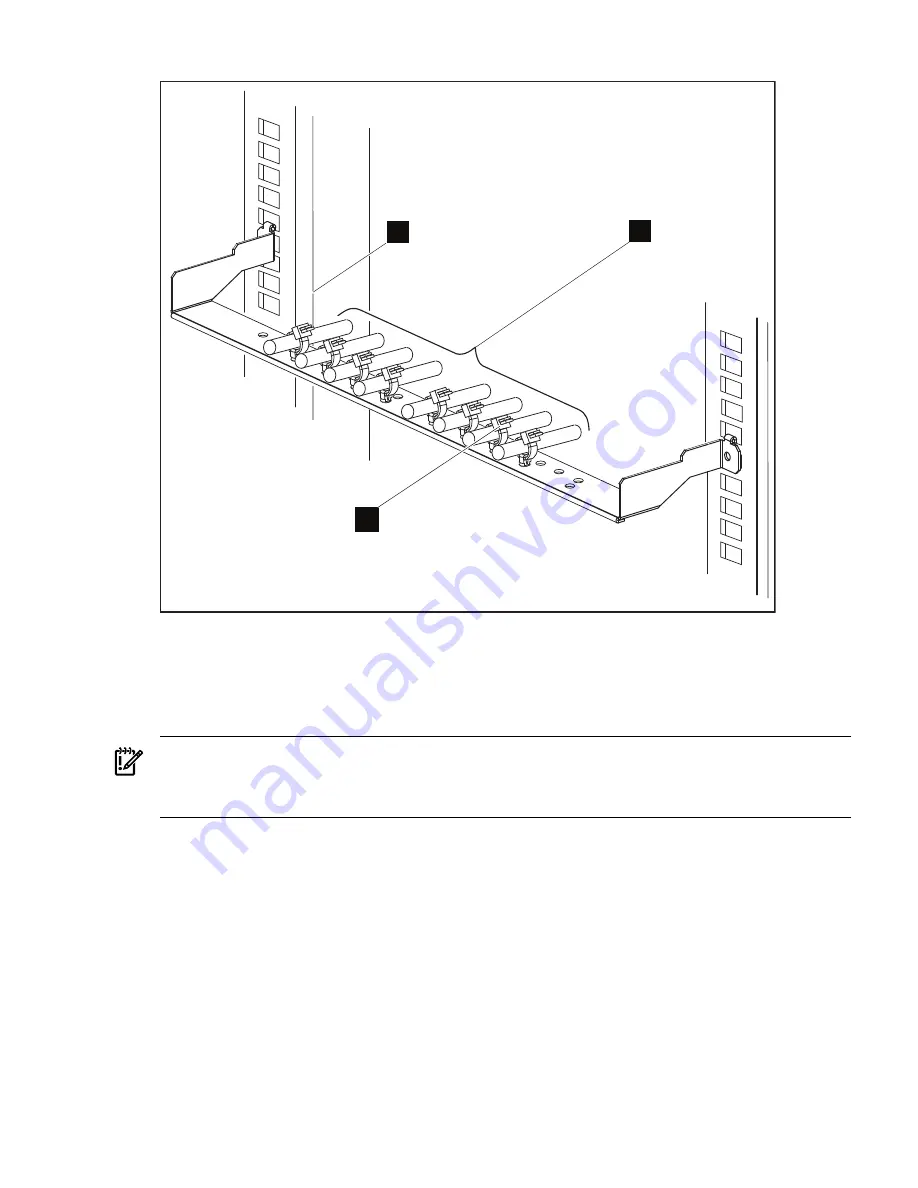
Figure 3-2 A Cable Management Bracket Holding 8 InfiniBand Uplink Cables
1
3
2
The following list describes the callouts shown in
Figure 3-2
:
1.
Left rear rack column
2.
8 secured InfiniBand cables
3.
One of the 8 releasable cable ties (completed assembly)
Important:
You must install the HP BladeSystem c-Class enclosure cable management bracket to provide
proper strain relief for the InfiniBand cables.
To install the InfiniBand cables and secure them with the releasable cable ties, follow these steps:
1.
Depending on the type of c-Class InfiniBand switch you have (see
Figure 3-1
and
Figure 3-2
),
determine the appropriate holes to install the push-button mounts. The row of holes closest
to the InfiniBand switch are used for the 16 uplink port InfiniBand switch. The row of holes
furthest out from the switch are used for the 8 uplink port InfiniBand switch.
2.
Install the push-button mounts by pressing them upward into each hole in the cable
management bracket for your InfiniBand switch type (see callout 4 in
Figure 1-1
).
3.
Cable the lower InfiniBand switch first, as described in the HP BLc 4X DDR InfiniBand Gen
2 Switch Installation Guide.
4.
To secure an InfiniBand cable (callout 1 in
Figure 3-3
) to the cable management bracket,
slide the releasable cable tie through the push button mount and around the InfiniBand
cable (see callout 2 in
Figure 3-3
) and through the releasable cable tie lock.
3.2 Installing the Releasable Cable Ties for the InfiniBand Cables
15
Summary of Contents for BladeSystem c-Class Enclosure Cable Management Bracket
Page 6: ...6 ...
Page 10: ...10 ...
Page 19: ...19 ...
Page 20: ... 436670 doc Printed in the US ...


