35
ARP MAD detection-enabled IRF configuration example
Network requirements
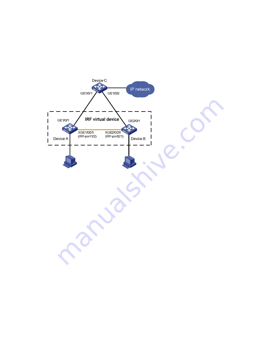
The network (see
Figure 15
) is outgrowing the forwarding capability of the existing core switch Device
A. To accommodate to business growth, the network must be scaled up to extend its forwarding
capability while the present network investments are protected. In addition, the ease of management
and maintenance must be ensured.
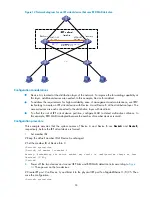
Figure 15
Network diagram for an IRF virtual device that uses ARP MAD detection
Configuration considerations
•
Device A is located at the distribution layer of the network. To improve the forwarding capability at
this layer, additional devices are needed. In this example, Device B is added.
•
To address the requirements for high availability, ease of management and maintenance, use IRF2
technology to create an IRF virtual device with Device A and Device B at the access layer. The IRF
virtual device is connected to Device C with dual links.
•
To offset the risk of IRF virtual device partition, configure MAD to detect multi-active collisions. In
this example, ARP MAD is adopted because the number of members in the IRF virtual device is
small, and the ARP MAD packets are transmitted over dual links connected to Device C. Enable
MSTP on the IRF virtual device and Device to prevent loops.
Configuration procedure
This example assumes that the system names of Device A, Device B and Device C are
DeviceA
,
DeviceB
,
and
DeviceC
, respectively, before the IRF virtual device is formed.
1.
Set member IDs
# Keep the default member ID of Device A unchanged.
# Set the member ID of Device B to 2.
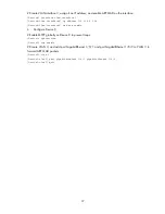
<DeviceB> system-view
[DeviceB] irf member 1 renumber 2
Warning: Renumbering the switch number may result in configuration change or loss.
Continue? [Y/N]:y
[DeviceB]


