32
4.
Configure LACP MAD detection
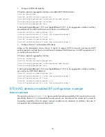
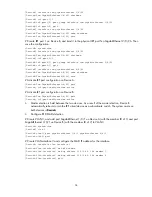
# Create a dynamic aggregation interface and enable LACP MAD detection.
<DeviceA> system-view
[DeviceA] interface bridge-aggregation 2
[DeviceA-Bridge-Aggregation2] link-aggregation mode dynamic
[DeviceA-Bridge-Aggregation2] mad enable
[DeviceA-Bridge-Aggregation2] quit
# Add ports GigabitEthernet 1/0/1 and GigabitEthernet 2/0/1 to the aggregation interface and they
are dedicated to the LACP MAD detection for Device A and Device B.
[DeviceA] interface gigabitethernet 1/0/1
[DeviceA-GigabitEthernet1/0/1] port link-aggregation group 2
[DeviceA-GigabitEthernet1/0/1] quit
[DeviceA] interface gigabitethernet 2/0/1
[DeviceA-GigabitEthernet2/0/1] port link-aggregation group 2
5.
Configure Device C as the intermediate device
Acting as the intermediate device, Device C needs to support LACP to forward and process LACP
protocol packets, and help Device A and Device B implement MAD detection. An LACP-supported switch
is used here to save the cost.
# Create a dynamic aggregation interface.
<DeviceC> system-view
[DeviceC] interface bridge-aggregation 2
[DeviceC-Bridge-Aggregation2] link-aggregation mode dynamic
[DeviceC-Bridge-Aggregation2] quit
# Add ports GigabitEthernet 1/0/1 and GigabitEthernet 1/0/2 to the aggregation interface and they
are used for the LACP MAD detection.
[DeviceC] interface gigabitethernet 1/0/1
[DeviceC-GigabitEthernet1/0/1] port link-aggregation group 2
[DeviceC-GigabitEthernet1/0/1] quit
[DeviceC] interface gigabitethernet 1/0/2
[DeviceC-GigabitEthernet1/0/2] port link-aggregation group 2
BFD MAD detection-enabled IRF configuration example
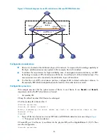
Network requirements
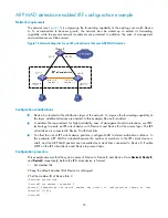
The network as shown in
Figure 14
is outgrowing the forwarding capability of the existing core switch,
specifically, Device A. To accommodate business growth, the network must be scaled up to extend its
forwarding capability while the present network investments are protected. In addition, the ease of
management and maintenance must be ensured.


