33
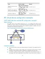
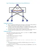
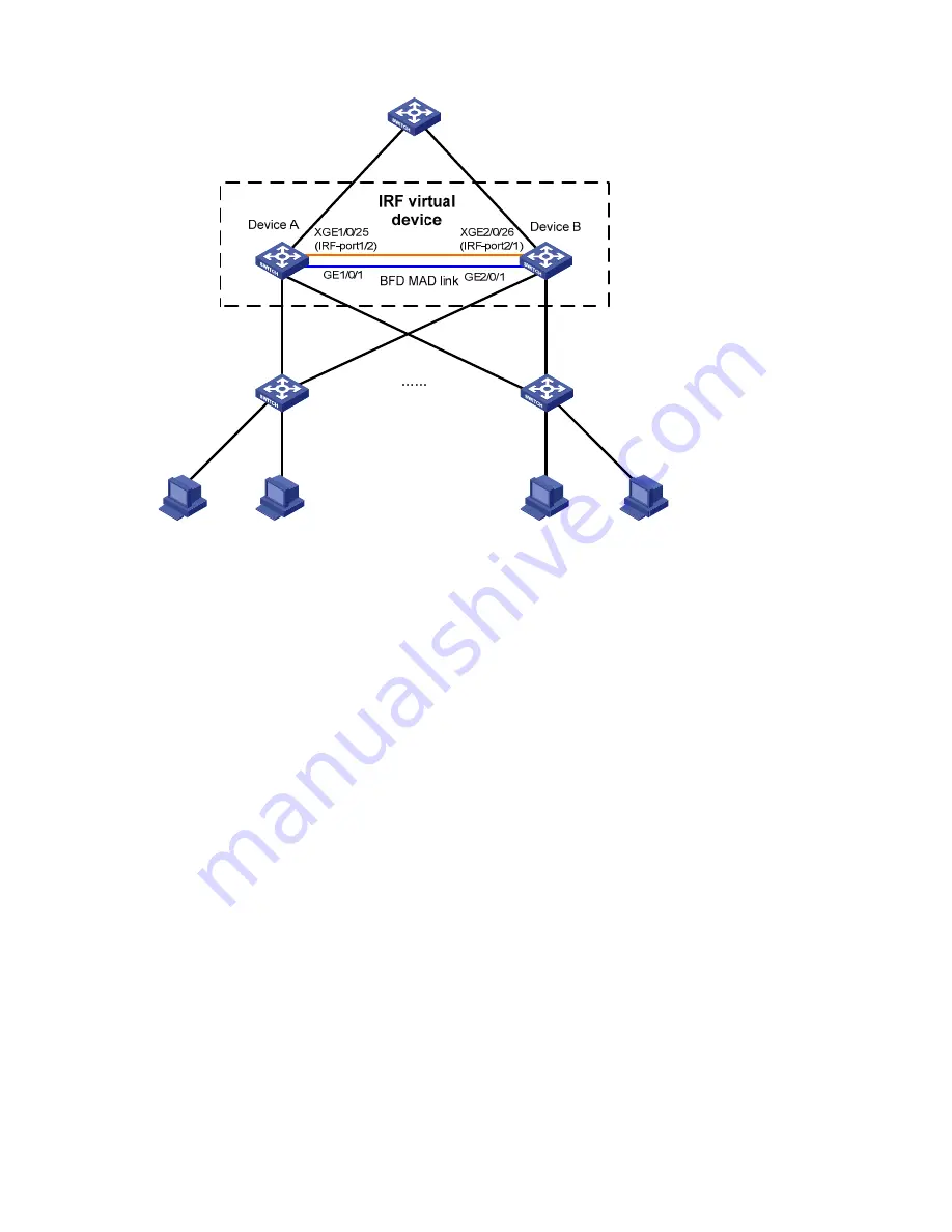
Figure 14
Network diagram for an IRF virtual device that uses BFD MAD detection
Configuration considerations
•
Device A is located at the distribution layer of the network. To improve the forwarding capability at
this layer, additional devices are needed. In this example, Device B is added.
•
To address the requirements for high availability, ease of management and maintenance, use IRF2
technology to create an IRF virtual device with Device A and Device B at the distribution layer. The
access devices are each connected to the distribution layer with dual links.
•
To offset the risk of IRF virtual device partition, configure MAD to detect multi-active collisions. In
this example, BFD MAD is adopted because the number of member devices is small.
Configuration procedure
This example assumes that the system names of Device A and Device B are
DeviceA
and
DeviceB
,
respectively, before the IRF virtual device is formed.
1.
Set member IDs
# Keep the default member ID of Device A unchanged.
# Set the member ID of Device B to 2.
<DeviceB> system-view
[DeviceB] irf member 1 renumber 2
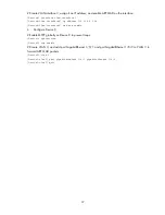
Warning: Renumbering the switch number may result in configuration change or loss.
Continue? [Y/N]:y
[DeviceB]
2.
Power off the two devices and connect IRF links and BFD MAD detection links according to
Figure
14
. Then power on the two devices.
# Create IRF port 2 on Device A, and bind it to the physical IRF port Ten-GigabitEthernet 1/0/25. Then
save the configuration.
<DeviceA> system-view


